PRODUCT INFO Asus ROG Strix Z370-E Gaming X Motherboard Manufacture Asus Available at View at Amazon
A never too late is what we would call this content as we look upon the Asus Strix Z370-E Gaming Motherboard for review. The Z370-E is the high-end motherboard in the ROG Strix lineup and it supports Intel 14nm CPUs under CoffeeLake. This motherboard has Asus AURA Sync digital RGB and 12V RGB headers along with M.2 onboard heatsink. It is equipped with Asus 5-Way optimization topology to auto-tune the System for better performance. This motherboard has out-of-the-box support for high-speed Non-ECC, Unbuffered RAM of up to 4000MHz (O.C). It supports Nvidia 2—Way SLI and AMD 3-Way CrossFireX. It features Intel 1219V NIC for better gaming networking. It has ROG SupremeFX 8-Channel High Definition Audio Codec S1220A for better gaming audio. Above all, it has a built-in WiFi module with an ROG-designed stylish antenna.
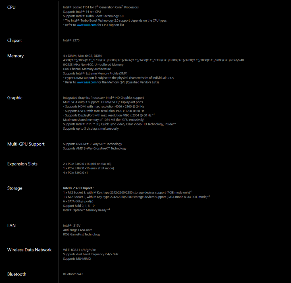
Specification
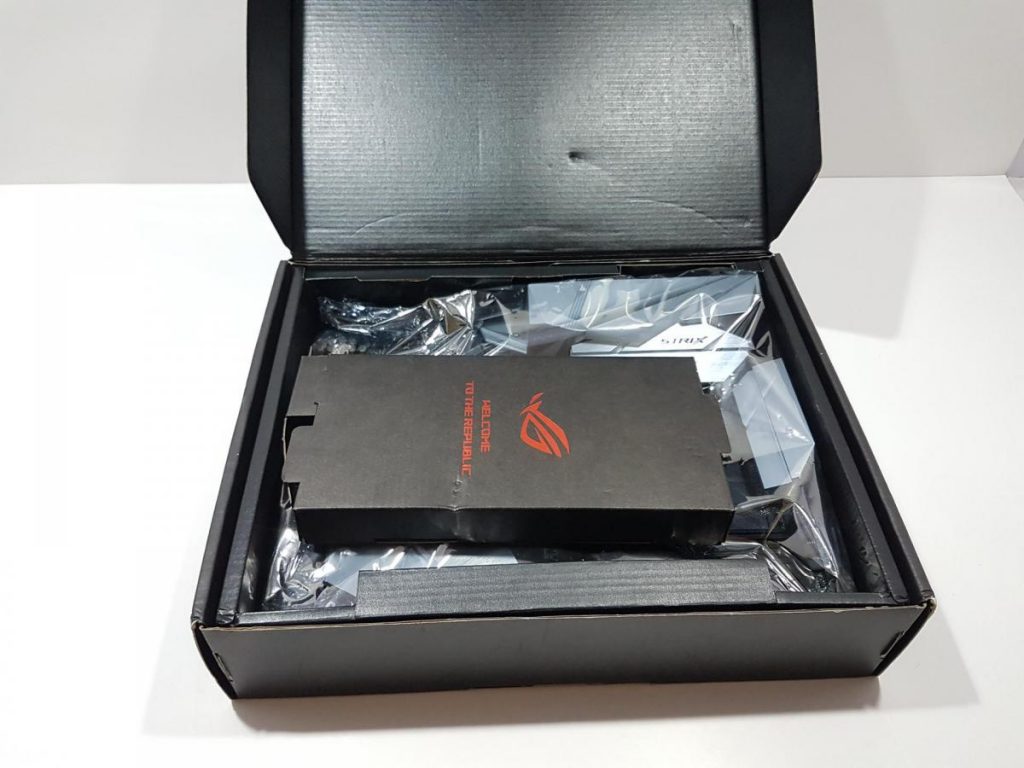
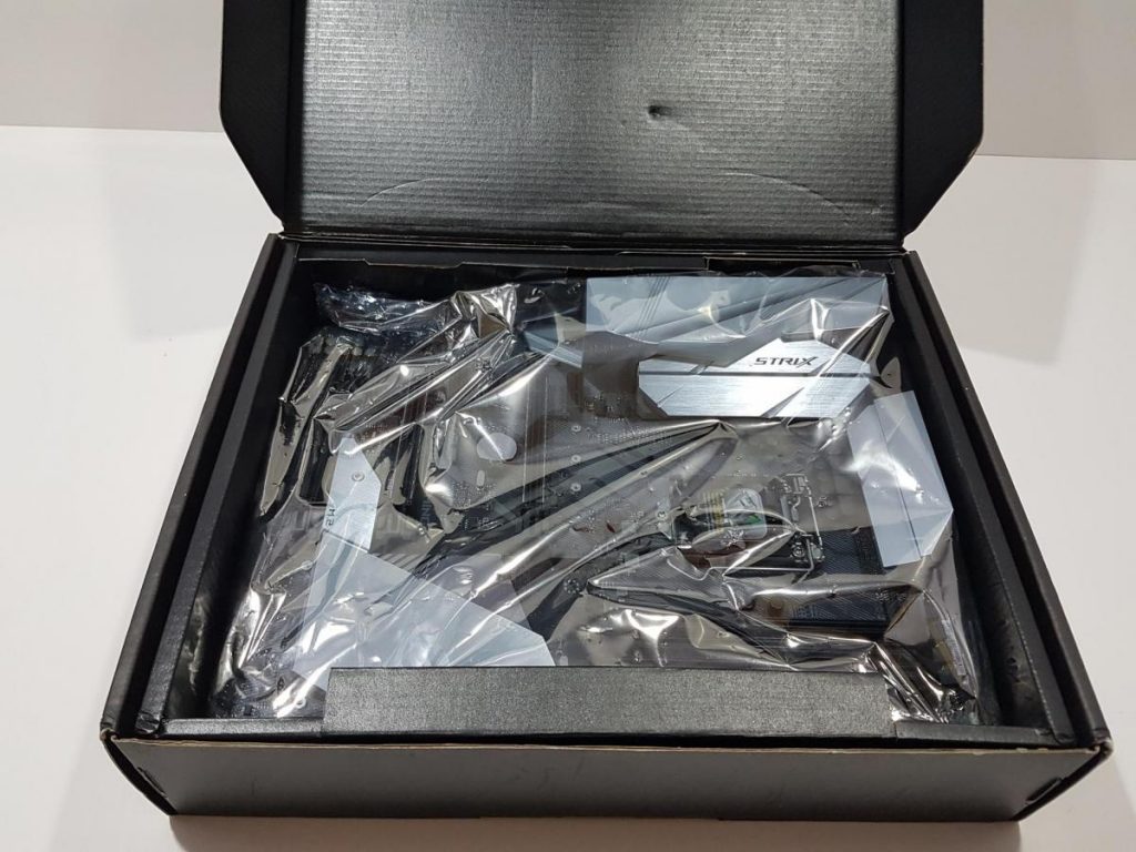
Packaging and Unboxing
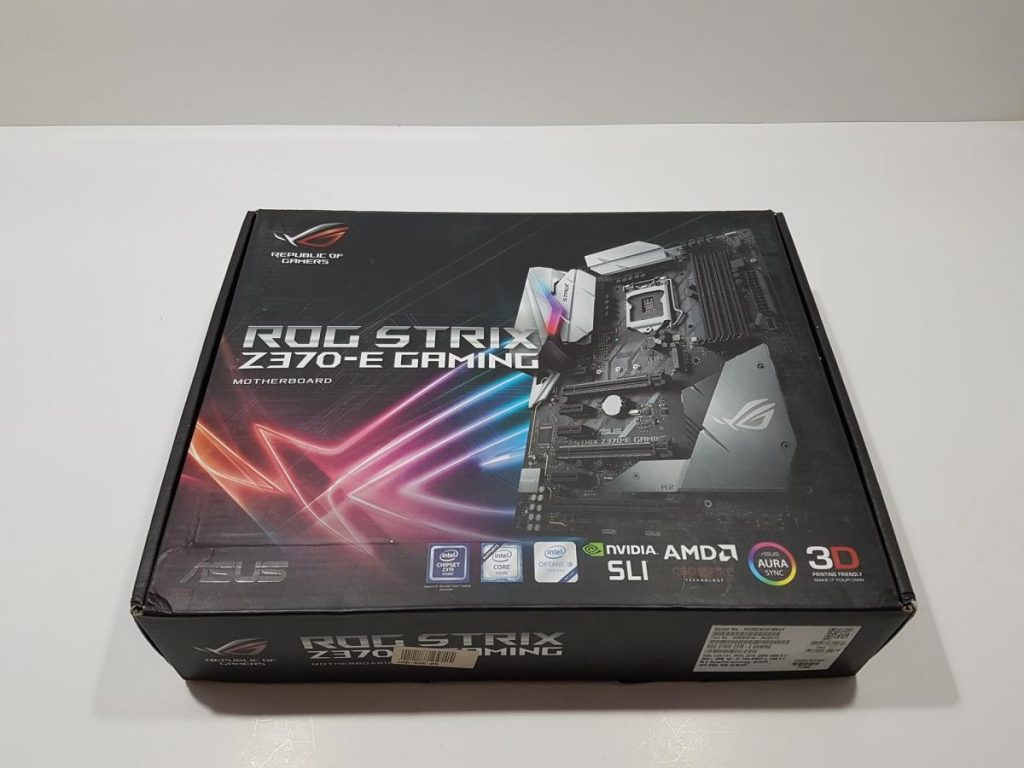
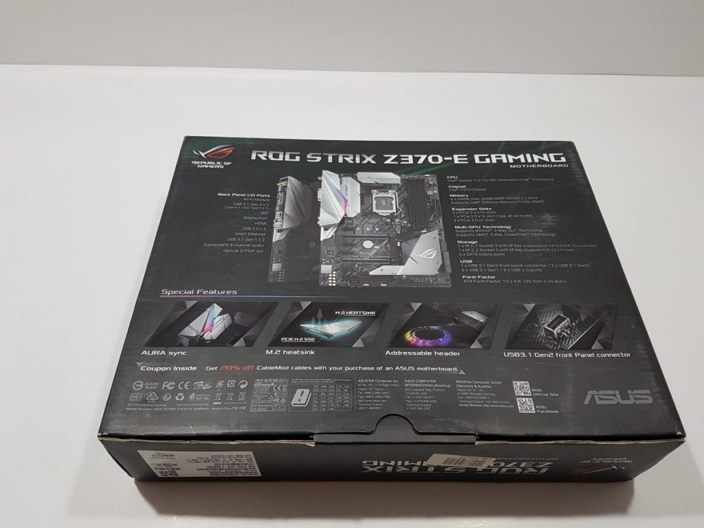
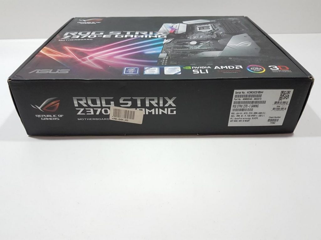
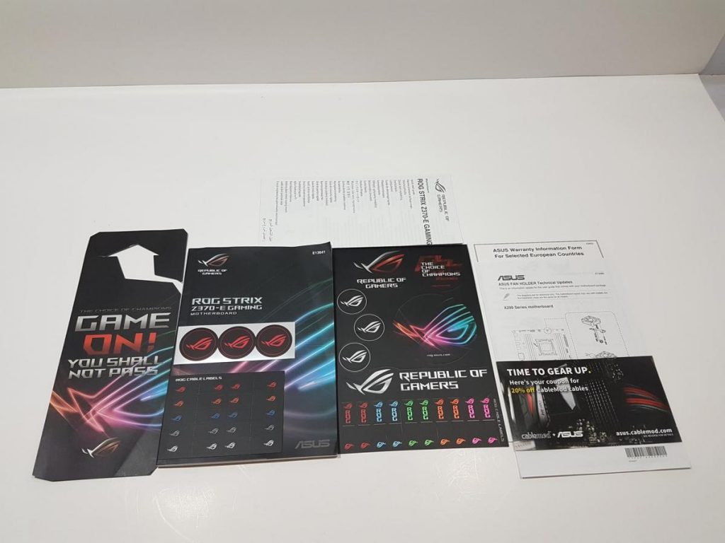
The motherboard comes inside a cardboard box with Asus branding. The top cover has the Asus Republic of Gamers brand name and logo printed on the top left side. There is a picture of the motherboard on the right side. ROG Strix Z370-E Gaming motherboard is printed on the picture’s left side.This motherboard supports the Intel Z370 chipset and is Optane Memory ready. It is Asus 3D printing friendly as well as has AURA Sync headers for some immersive lighting effects. The backside of the box has Asu Republic of Gamers brand name and logo printed on the top left side followed by the ROPG Strix Z370-E Gaming Motherboard line. There are two pictures of the motherboard one showing the rear I/O ports and the other showing the front of the board.
The salient specifications of the motherboard are printed on the sides of these pictures. Special features such as AURA Sync, M.2 Heatsink, Addressable Header, and USB 3.1 Gen2 Front Panel Connector are printed below the pictures. There is a 20% off CableMod Coupon inside the box as well. The company’s contact info is printed at the bottom. The left and right sides have identical layouts and printing.
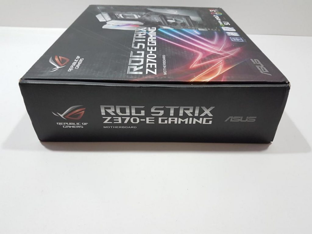
The Asus Republic of Gamers brand name and logo are printed on the leftmost side followed by the ROG Strix Z370-E Gaming Motherboard in the middle and Asus on the rightmost side. The front cover has the Asus Republic of Gamer brand name and logo printed on the left side followed by the ROG Strix Z370-E Gaming Motherboard. There is a large sticker pasted on the right side.
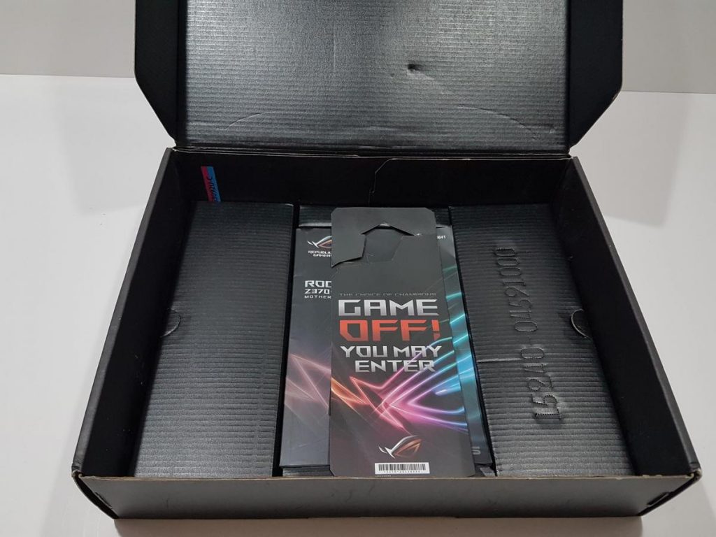
Accessories
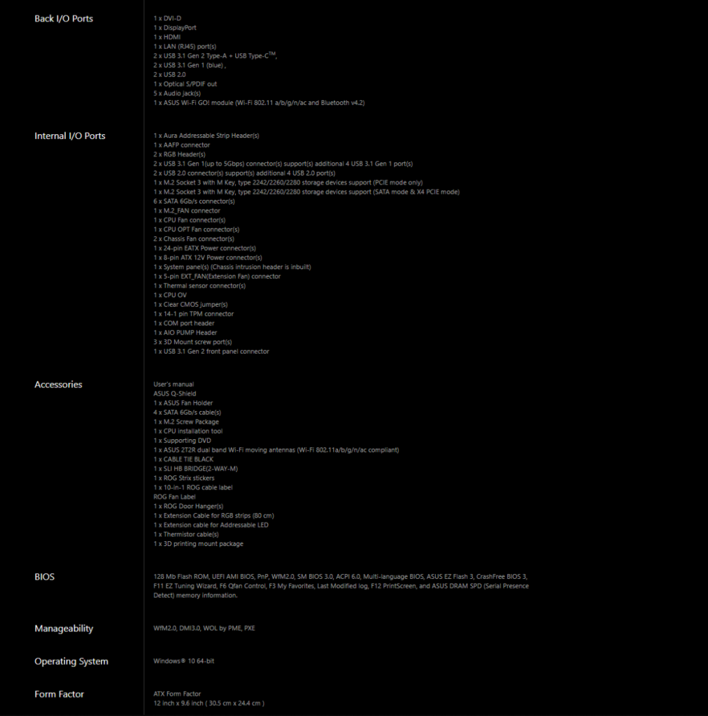
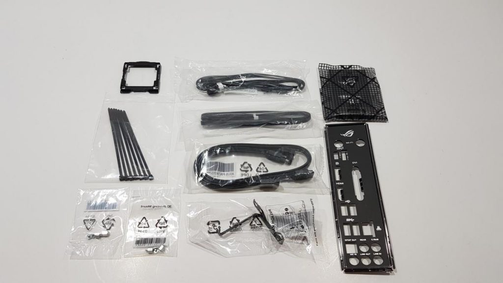
Accessories included with the motherboard are:-- User’s manual
- ASUS Q-Shield
- 1 x ASUS Fan Holder
- 4 x SATA 6Gb/s cable(s)
- 1 x M.2 Screw Package
- 1 x CPU installation tool
- 1 x Supporting DVD
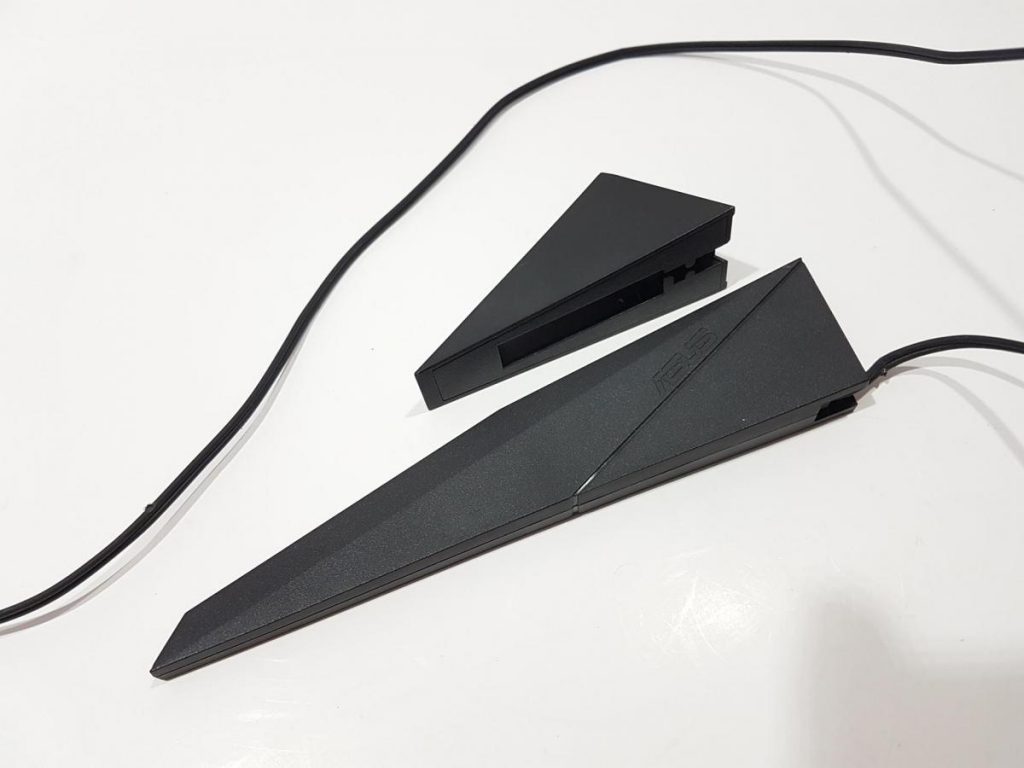
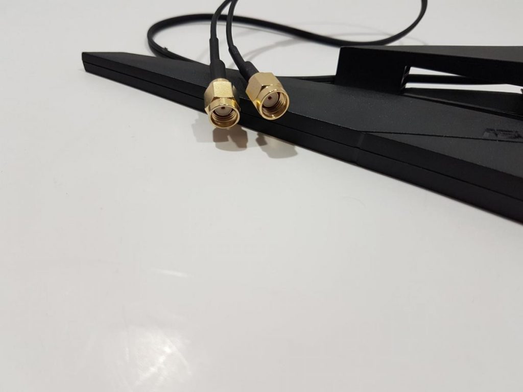
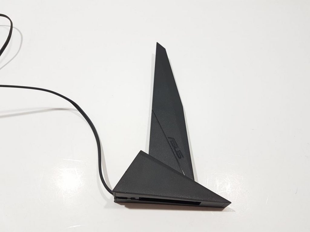
- 1 x ASUS 2T2R dual band Wi-Fi moving antennas (Wi-Fi 802.11a/b/g/n/ac compliant)
- 1 x CABLE TIE BLACK
- 1 x SLI HB BRIDGE(2-WAY-M)
- 1 x ROG Strix stickers
- 1 x 10-in-1 ROG cable label
- ROG Fan Label
- 1 x ROG Door Hanger(s)
- 1 x Extension Cable for RGB strips (80 cm)
- 1 x Extension cable for Addressable LED
- 1 x Thermistor cable(s)
- 1 x 3D printing mount package
Closer Look
We will be taking a look at the motherboard and discussing the key features along the main sections of the design elements. Here is what Asus is saying about it, “With aesthetics inspired by the sharpest blades and premium colorways to match any mood, the all-new ROG Strix Z370 motherboards are ready to do battle — and infused with all the essential ROG engineering needed to push performance as far as you dare.
The Intel® Z370 chipset supports 8th Generation Intel® Core™ processors. It provides improved performance by utilizing serial point-to-point links, allowing increased bandwidth and stability. Additionally, the Z370 provides a maximum of 10 USB 3.1 Gen 1 port, six SATA 6Gbps ports, and 32Gbps M.2 and PCIe 3.0 lane speed support, for faster data retrieval. Intel Z370 also supports integrated graphics.
ROG Strix Z370-E Gaming is loaded with overclocking and cooling innovations to keep your gaming rig’s thermals in check as you turn up the clock. Factor in custom Aura RGB illumination and superior SupremeFX audio and you’ll know that ROG Strix Z370-E Gaming looks great and sounds amazing — and outperforms every expectation to dominate your game!”
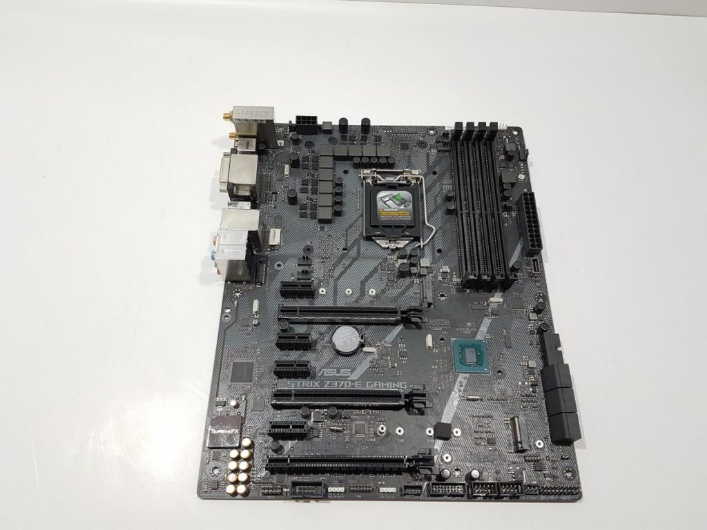
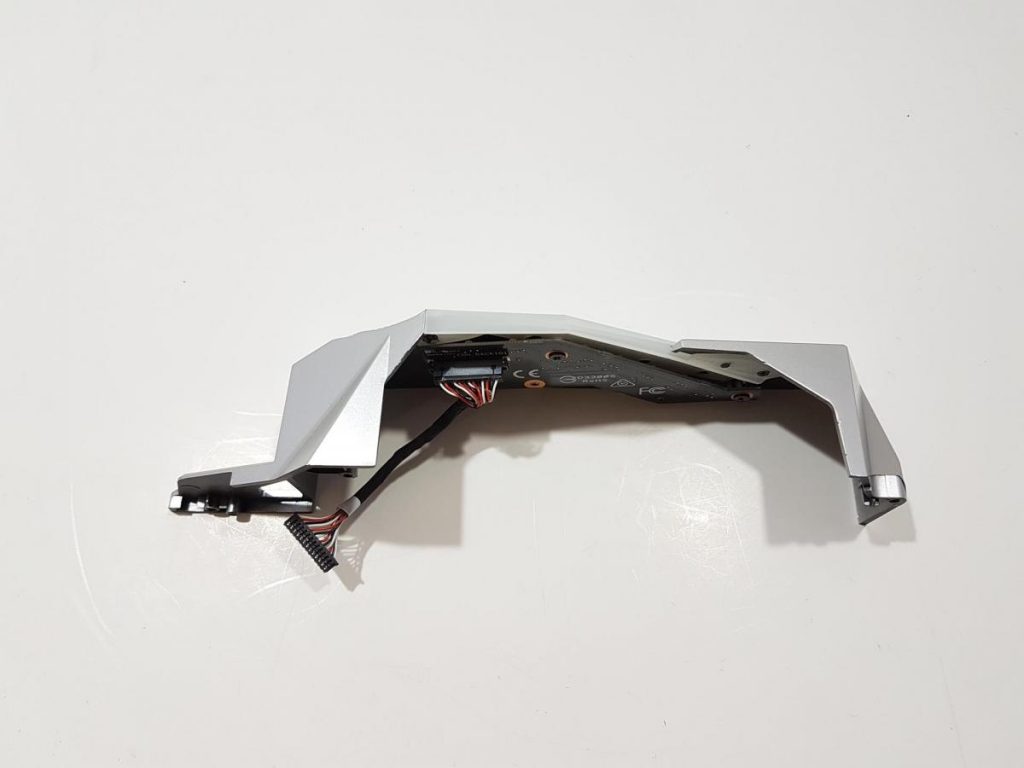
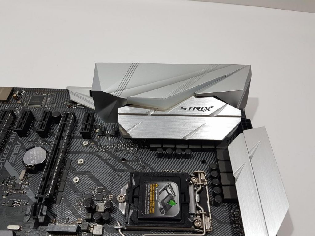
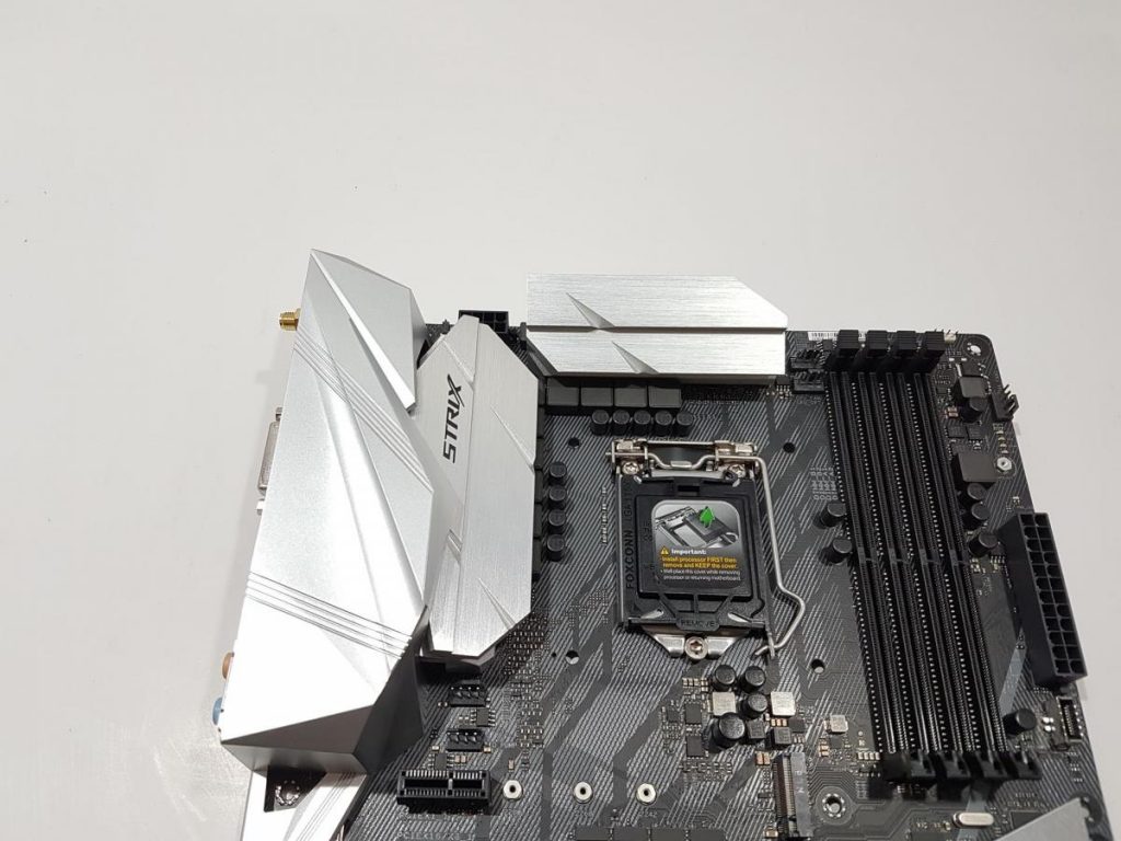
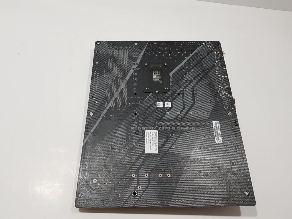
This motherboard has a standard ATX size PCB (12”x9.6”) which is in black color. The wire traces are beautifully designed on the PCB as they are visible and add to the overall aesthetics and beauty of the board. The left top side has a silver color plastic-made shroud covering the rear I/O ports.
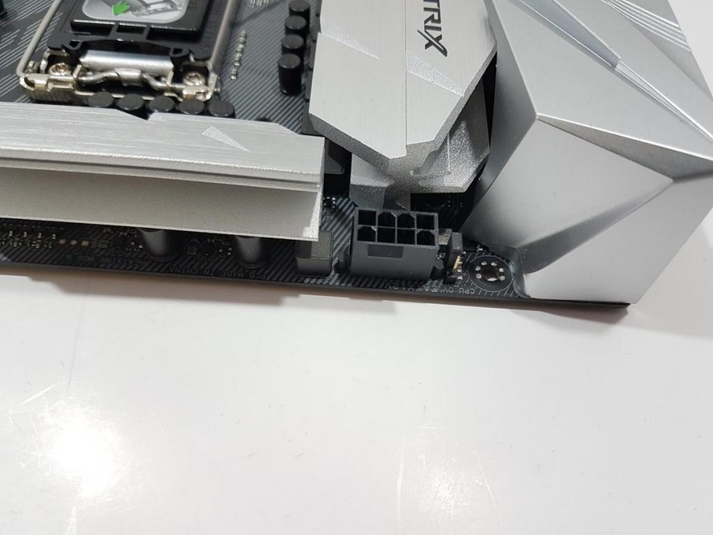
It has got a bold-looking design to it with curves, edges, and lines. There is a diffuser on its top side facing the CPU socket. The diffuser part of the shroud is covering a certain portion of the VRM aluminum heatsink. If you would look closely there are cutouts on both VRM heatsinks. These cutouts illuminate from the light coming off the diffuser and create one heck of an impressive look when in action.
There are gray color thermal pads on the back sides of these heatsinks that come in contact with the VRM and MOSFETs to dissipate the heat from them. Each heatsink is stylishly designed and comes from a single piece of aluminum.
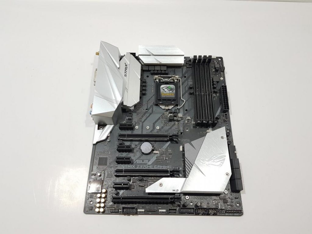
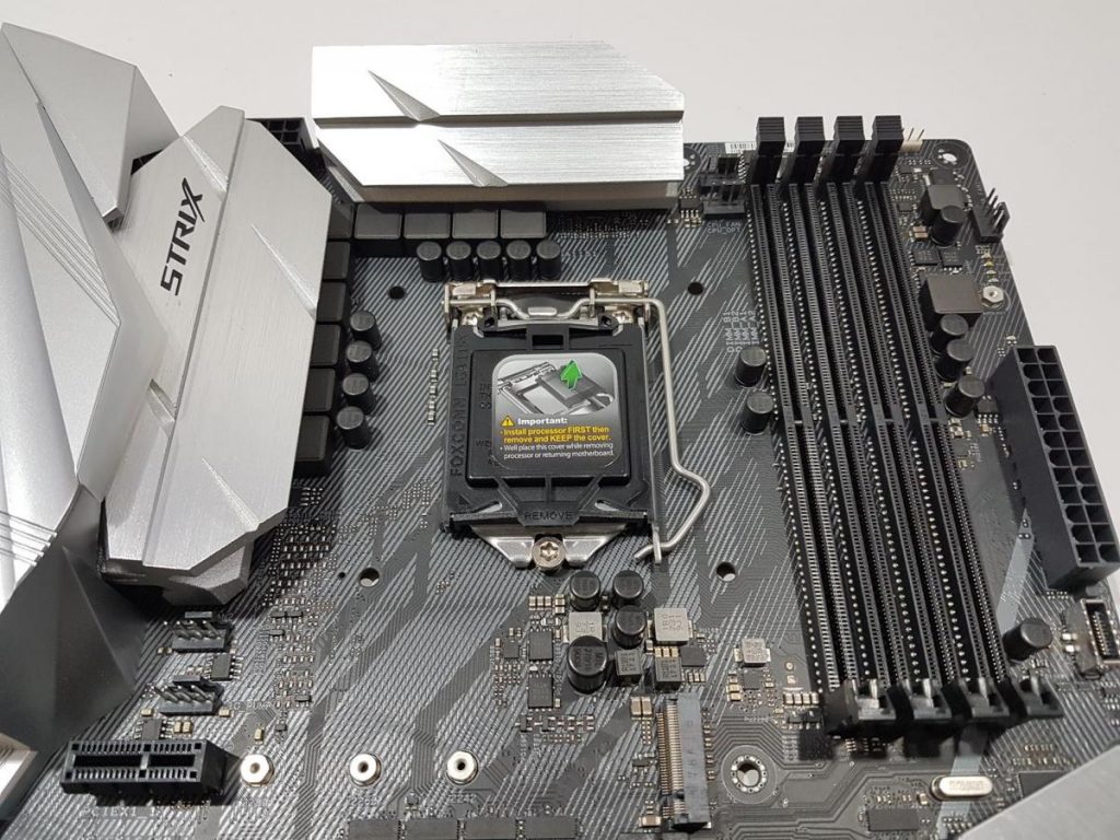
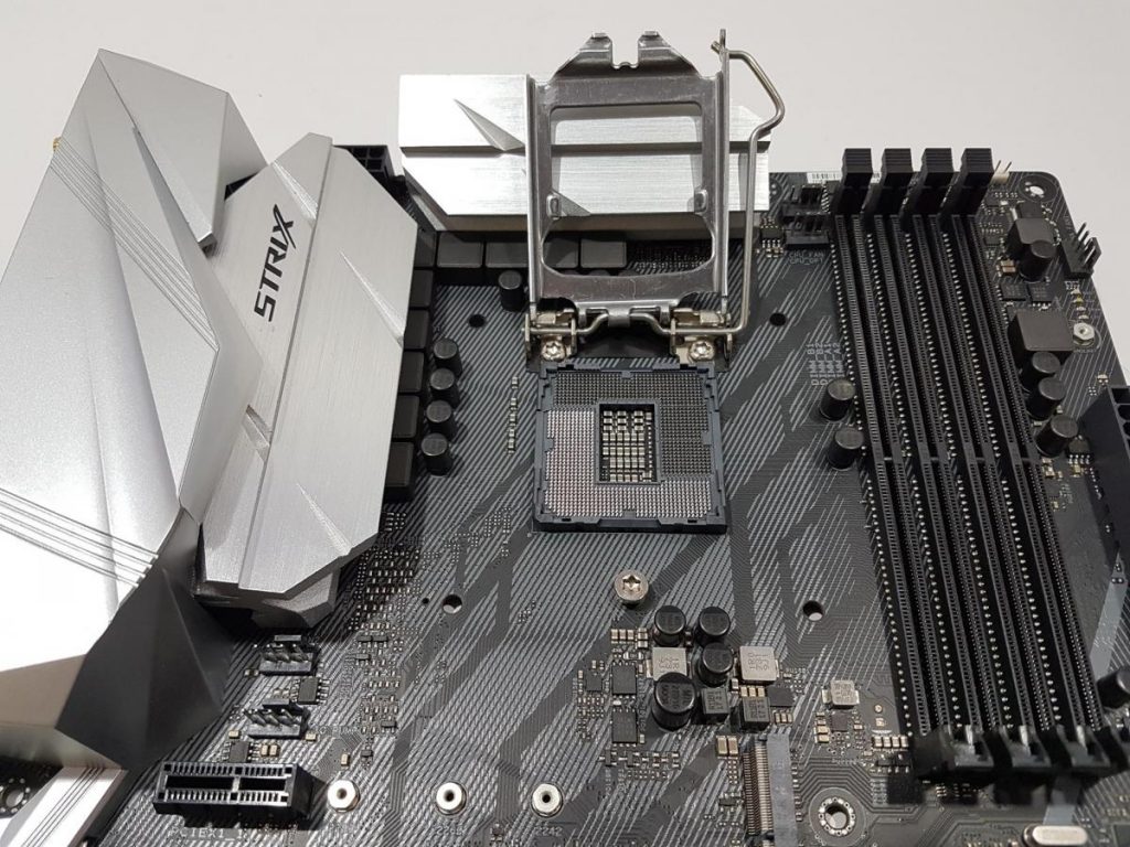
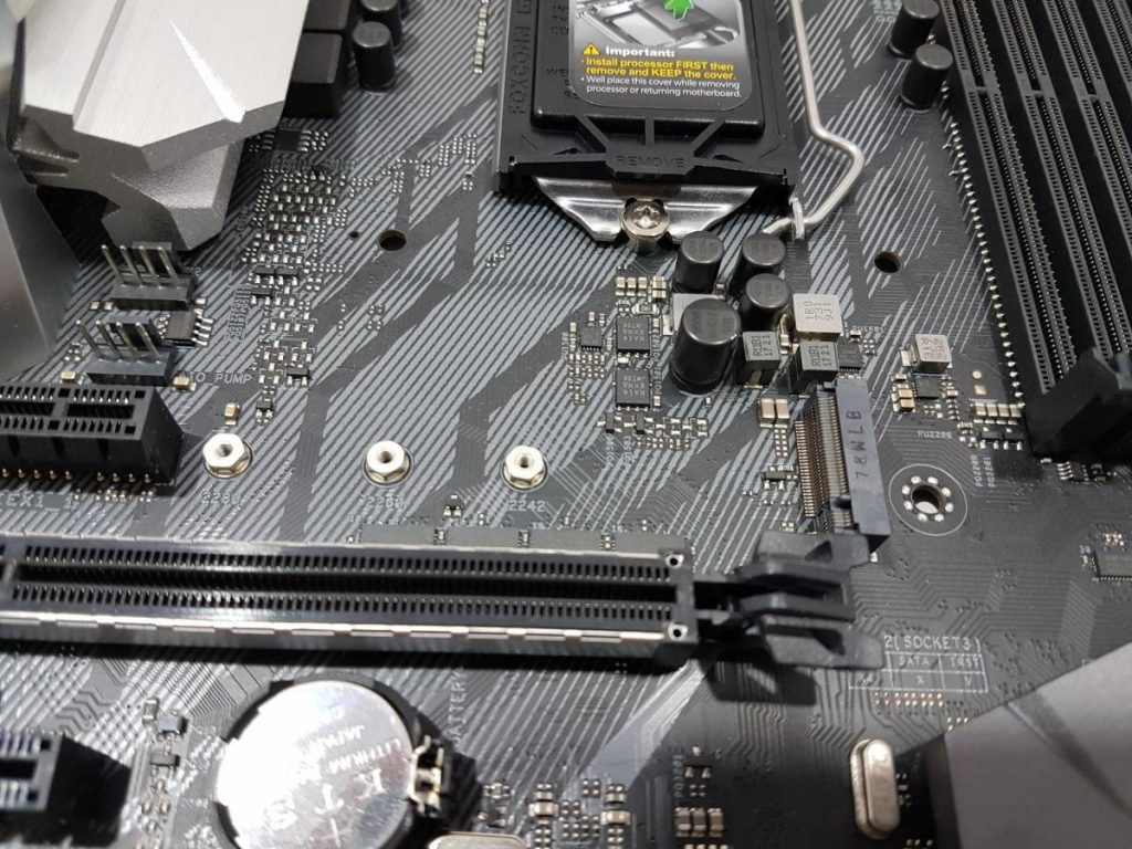
This board features the Intel LGA-1151 socket. Don’t be confused with the socket type as you can’t use Skylake/Kabylake-based CPUs on the 8th-generation motherboards. Though the no of pins is the same their specific operation is not. It is well designed with clearance in mind for large CPU coolers. Foxconn LGA115X is printed on the CPU socket cover. Important instructions are printed on the top of the socket cover. This cover needs to be placed somewhere safe after installing the CPU. As a general rule of thumb, always keep the CPU socket cover.
PCB
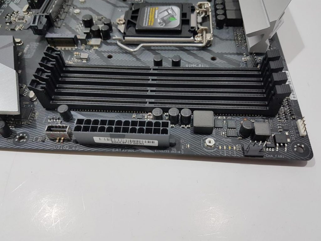
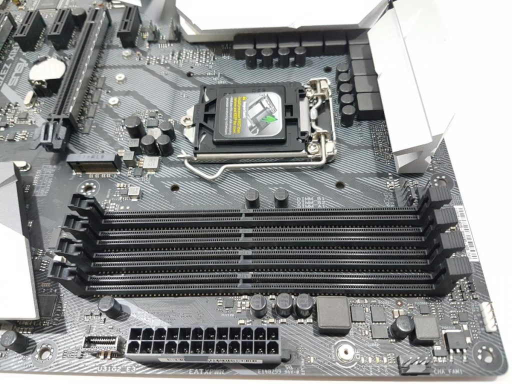
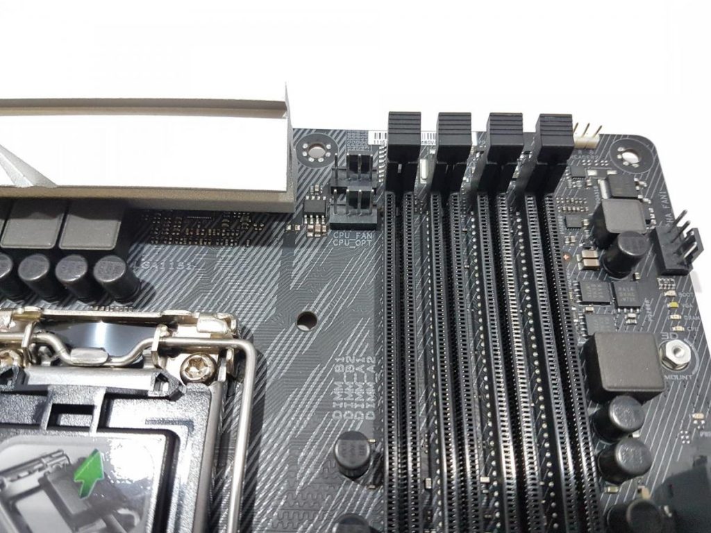
Taking a look at the top of the PCB, starting from the left side there is a 3-pin CPU over voltage jumper with a default setting of disabled as the jumper is in pins no 1 and 2. This jumper allows boosting more voltage to the CPU for better and more stable overclocking. Use it only if you know your stuff. To enable this header, remove the jumper and put it on pins no 2 and 3. Right next to it is an 8-pin EATX12V connector or commonly known as CPU power header/EPS connector. Following the line from this connector to the further right side, we come across two fan headers. These are CPU fan header and CPU Optional Fan header from top to bottom. Each of them is a 4-pin PWM header drawing 1A at 12V. The very last header on the top side is an AURA Sync header for a non-addressable RGB lighting solution. It has a +12V GRB pin format. The RGB header supports 5050 RGB multi-color LED strips with a maximum power rating of 3A at 12V and no longer than 3m.
RAM Modules
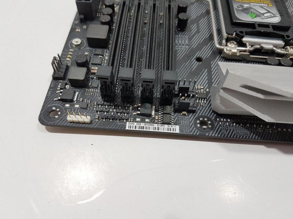
Down the road, we have 4 DIMM slots for DDR4-type memory only. One side has fixed latches whereas the other sides have flexible latches. Asus is using the Q terminology on their motherboards like Q-DIMMs, Q-LED Debug, etc. We have 12mm of spacing between the DIMM and the CPU socket area. This is calculated from the mounting holes on the socket area. To install a RAM, release/push the flexible latch outwards, align the pins on the RAM with the DIMM slot’s mounting area and insert the RAM into it, this will automatically pull the flexible latch to snap on the RAM and you will hear a nice clicking sound confirming that latch has locked on the RAM.
To remove the RAM, simply push that latch away from the RAM and pull out the RAM. A maximum of 4 DIMMs can be installed at a time with a maximum capacity of 64 GB. These are DDR4 types with 288 pins. DDR4 speed is 2133/2400/2666MHz as per JEDEC specification. The maximum supported speed on this motherboard is 4000 (OC) which is a bit shy of what we saw on the Asus ROG Maximus X Hero with 4133MHz (OC). Other supported speeds are already mentioned in the specification section of the review.
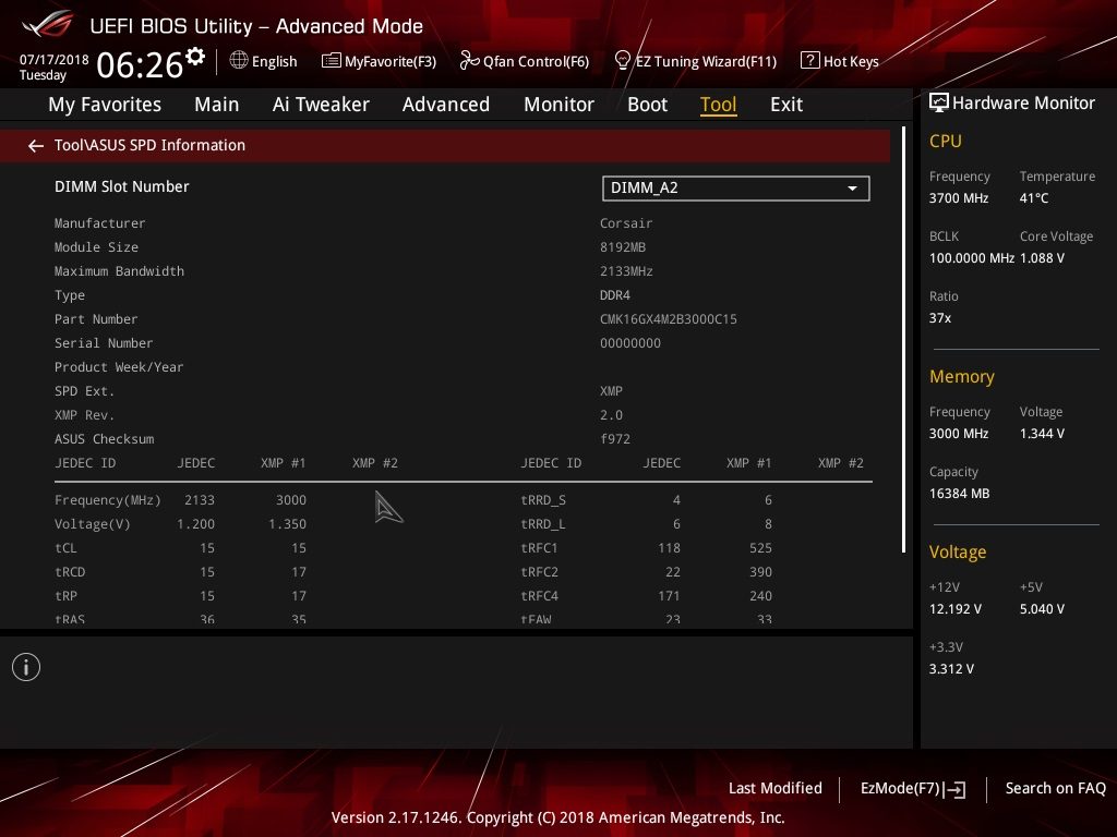
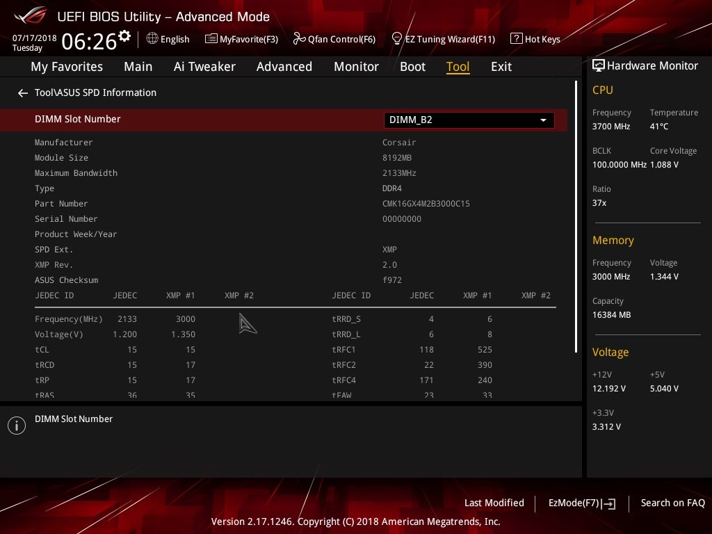
The memory type is Non-ECC, un-buffered with Dual Channel architecture. It supports Intel® Extreme Memory Profile (XMP). In case you are installing a single module, insert it into DIMM_A2 or the rightmost DIMM. For two modules, use the DIMM_B2 and DIMM_A2 slots. In other words, use the second and the fourth slot from the CPU socket. Adding all 4 modules needs no explanation.
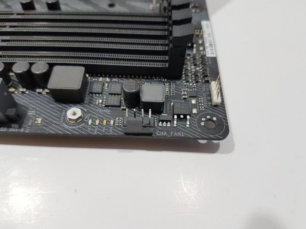
Fans and LEDs
Going further towards the right side, we have a 4-pin PWM fan header labeled as Channel Fan 1. This header is rated at 1A with 12V. Right below this fan header is 4 LEDs. Starting from the top we have Boot LED, VGA LED, DRAM LED, and CPU LED. The boot LED is in yellow-green color. The VGA LED is in white color. The DRAM LED is in yellow color. The CPU LED is in red color.
These are POST state LEDs as they provide the status of their respective key components during POST. In case of an issue/error, the corresponding LED will stay lit up until the issue is resolved. This is a visual aid for troubleshooting as this motherboard does not have Q-LED Debug.
There is a 3D mount under these LEDs. Asus with the release of the Kabylake series motherboards introduced a new feature known as 3D Printable Accessories. They have carried this design feature ever since with all the major releases and CoffeeLake-based motherboards are no exception to that. Now, users can customize the appearance of their builds using these 3D printable accessories. At the moment, 3D designs of these categories can be downloaded from the Asus website:
- 2-Way HB Bridge Cover
- Fan Grills
- Cable Combs
- ROG Fonts (Would come in handy for Apex users)
- ROG Keychain
Below the 3D point, there is another LED. It is called a standby power LED. This LED remains lit as long as the motherboard is getting power and serves as a reminder to the user to shut down the system.
USB Connections
Below this LED we have a 24-pin ATX power connector for the motherboard. Below this connector, we have a USB 3.1 Gen 2 front panel connector. Not all PC Chassis have support for this port at the moment but a few do. With the release of more and more new chassis, it is expected to become a norm much like USB 2.0/3.0 ports that are a common feature on the chassis.
The USB 3.1 Gen 2 allows up to 10Gbps transfer rate and it is compatible backward. Coming down further, we have USB 3.1 Gen 1 port which allows for additional USB 3.1 Gen 1 front or rear panel ports. The USB 3.1 Gen 1 has a data transfer rate of up to 5Gbps. One can use them for fast charging their USB devices provided those devices allow fast charging and this is fully compatible with USB 2.0 as well.
SATA Ports
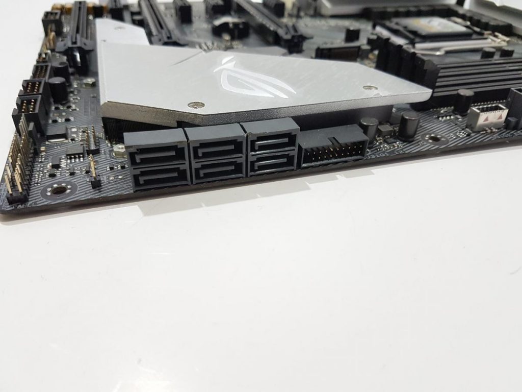
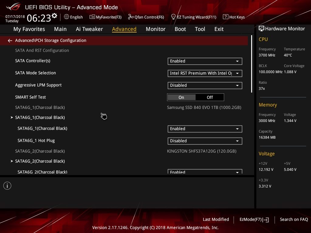
Below the USB 3.1 Gen 1 connector, we have 6 SATA ports which are 6Gb/s rated. RAID 0, 1, 5, and 10 configurations are possible from the Intel Z370 chipset using Intel Rapid Storage Technology. These ports are numbered from 1 to 6 where the top port right next to the USB 3.1 Gen 1 connector being port no 1 and its bottom port being no 2. These ports are by default set to AHCI mode in the BIOS.
Users can change that in the BIOS. For SATA disk drives, leave that mode as it is if not creating RAID. This motherboard is Intel Optane Memory ready. Right below the SATAW 6G ports, we have a Clear RTC RAM Jumper which is a two-pin CLRTC without any jumper on it. As there is no CMOS clear button on the rear I/O panel of this board, the only way to reset the BIOS is through this CLRTC.
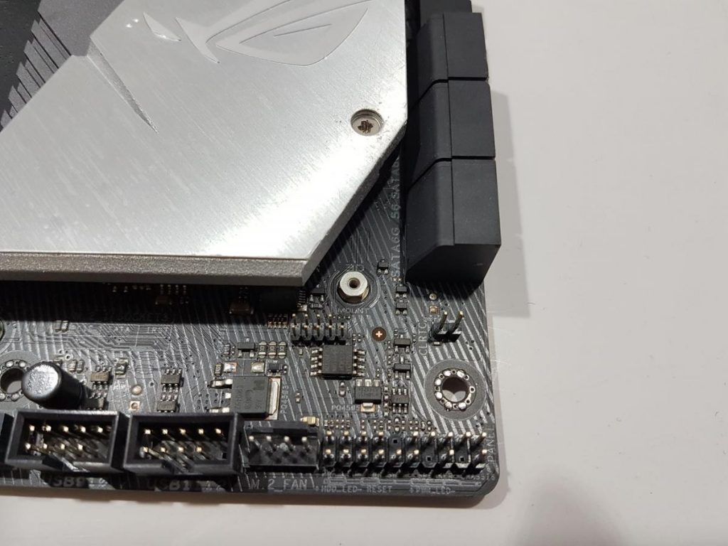
All that you need to do is to power down the system and touch both pins simultaneously using the flat head screwdriver’s tip once. That would clear the CMOS and the next boot will take you to the BIOS. The first pin is +3V and the next one is Ground. We have another 3D mount right behind the last two SATA 6G ports.
Power & Connectivity Options
Let’s take a look at the bottom section of the motherboard and see what connectivity options are there on it. Starting from the right side the first connector is the 20-3 pin system panel connector. This connector supports Chassis mounted functions like powering up the system, resetting it, Power LED indicator, storage LED indicator, etc. The top two leftmost pins are for the system power LED.
The first one is + polarity and the second one is – polarity. The system power LED lights up when the system is powered and it remains lit until the system is shut down or enters sleep mode. In sleep mode, this LED starts blinking. The first two bottom pins from the left side are for the HDD activity indicator. The first pin is + polarity and the second pin is – polarity. The third and fourth pins on the top from the left side are for the system power connector. The third pin is for the power button with the fourth one being ground.
The third and fourth pins on the bottom are for the reset button. The third pin is for ground and the fourth pin is for the reset button. The very last two pins on the last column on the right side are for the chassis intrusion function. Connect one end of the chassis intrusion sensor or cable to this connector. Now a day this is the least used option in home PCs. We also have a 4-pin speaker warning connector. Early systems had no visual indicators like Q LED Debug and Q LEDs that help in troubleshooting. Rather speaker was used commonly with no beeps indicating the corresponding troubled area. Nevertheless, the provision is still there should a user wants to use a warning speaker. Must be an old soul like me!
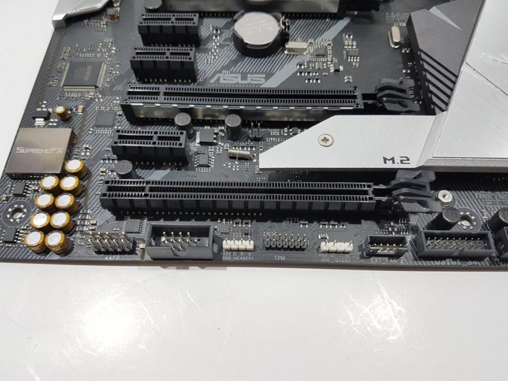
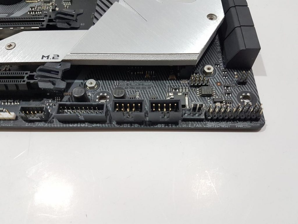
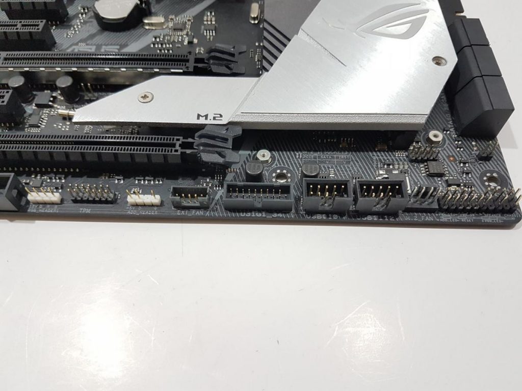
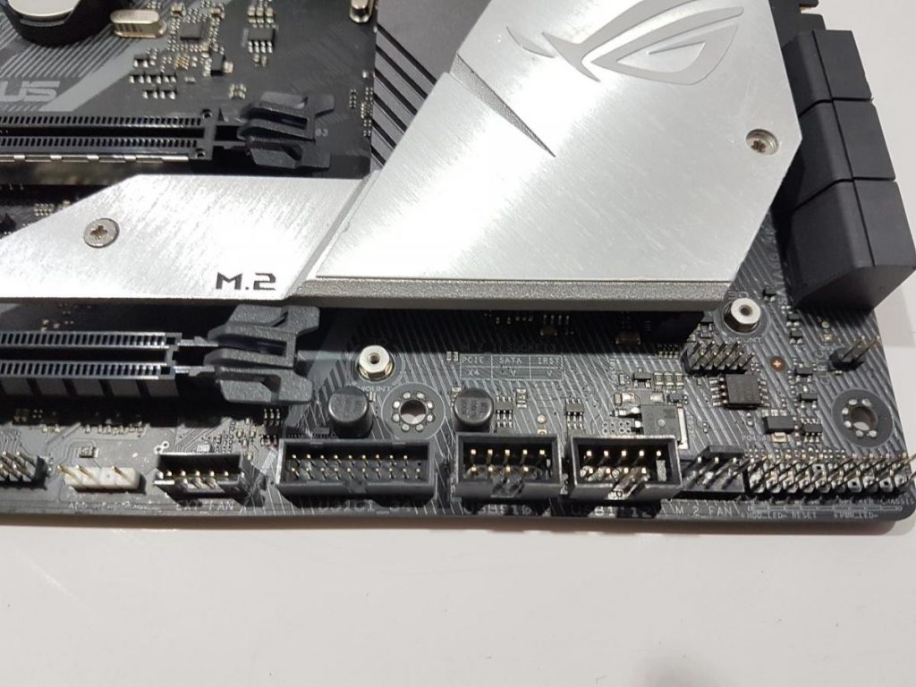
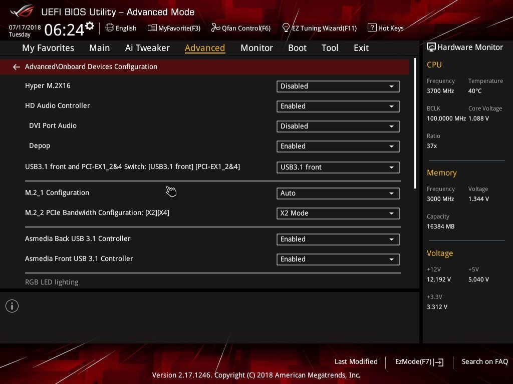
On the left side of the system panel connector, there is a 4-pin M.2 fan header. It seems like this header is set to regulate the connected fan based on the M.2 thermal sensor than the CPU. Users can mount the fan on the M.2 using the 3D printed bracket for this purpose and connect the fan to this header for speed regulation based on the M.2 thermals. Next, we have a fan header for M.2. we have two 10-1 pins USB 2.0 connectors.
These connectors comply with USB 2.0 specifications and are rated at 480Mb/s. Then we have a second USB 3.1 Gen 1 connector which is a 20-1 pin format. Next, we have a 5-pin Fan Extension connector. Should a user needs to connect and control more fans in the system, an optional Fan Extension accessory can be purchased which will allow connecting up to 3 PWM fans and 2 thermal sensors in addition to what is already on the motherboard. I love this idea from Asus though that would mean more cables to deal with and to properly mount the fan extension hub somewhere in the chassis. This hub has a SATA connector to power it up.
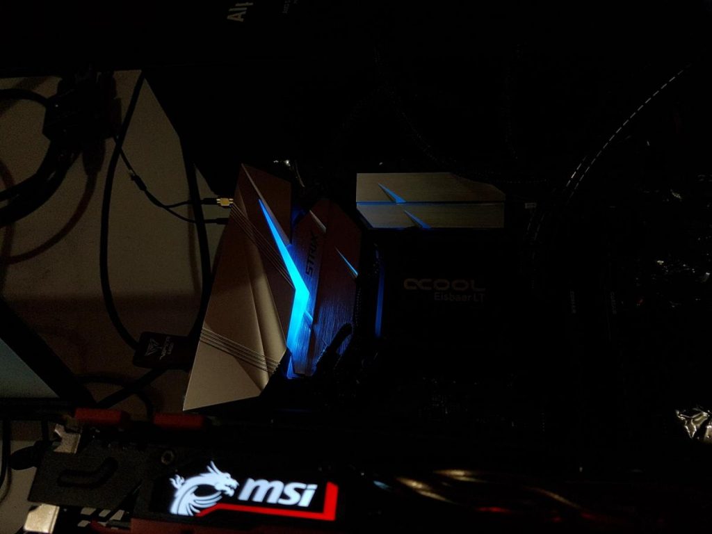
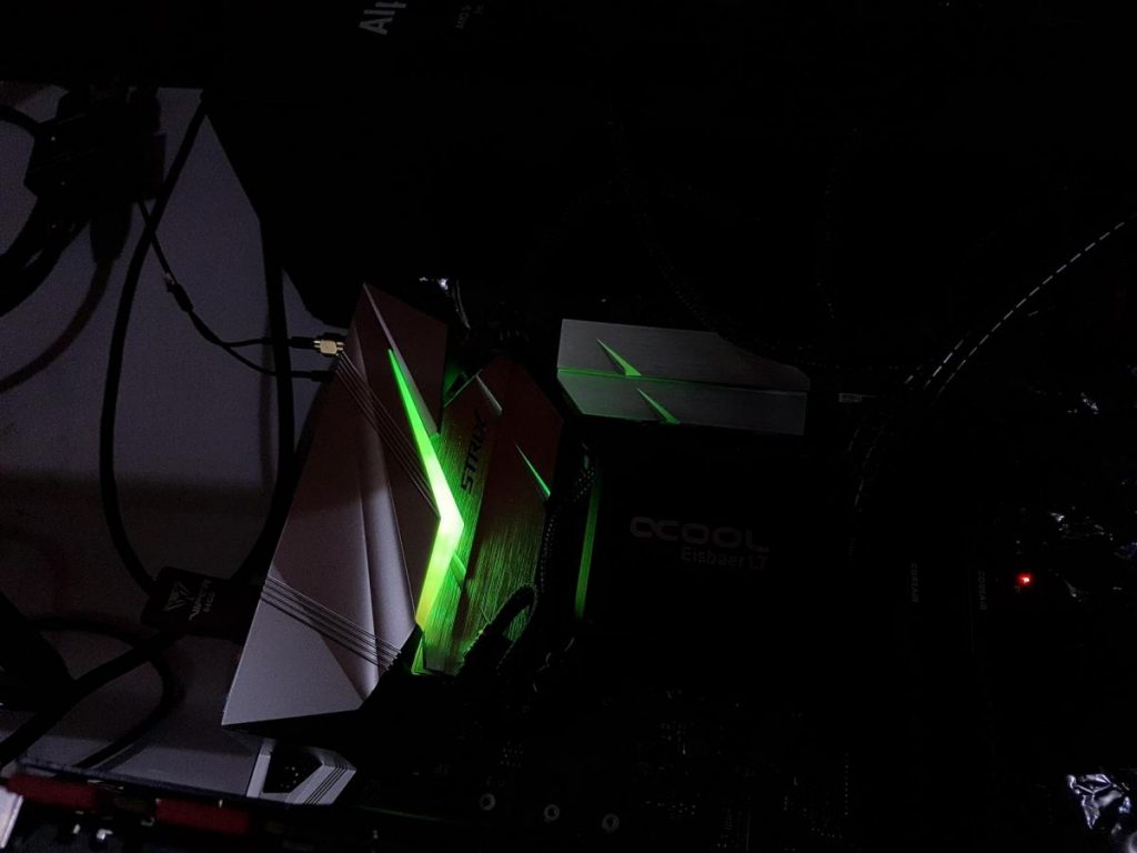
Right then, next, we have an addressable RGB header closely followed by a second AURA header. The addressable header is in 4-1 pin format. The first pin is +5V, the second pin is Data, no third pin, and the fourth pin is ground. This header supports WS2812B addressable RGB LED Strips with a maximum power rating of 3A at 5V and a maximum of 60 LEDs. Please, don’t connect the 5V LED on the 12V header as it would fry the LEDs easily. All this lighting comes under the AURA umbrella. As the name indicates, this technology has everything to do with the lighting on the board; not just lighting but RGB goodness.
Shroud on the back I/O ports has LEDs on the diffuser. Asus has provided software to control all the lighting effects. Users now can connect their LED strips specially designed for these headers with the motherboard and can have all the lighting of the chassis coordinated with the motherboard’s lighting effect. CableMod has designed many such strips for the AURA headers.
Anyone can do that by fulfilling the requirement which is 5050 RGB Multicolor LED Strips (12V/R/G/B) with a maximum power rating of 3A and no longer than 2m. I’ve one such designed LED strip with me as well for testing purposes. This board also has an addressable RGB LED header with (+5V/D//G).
This does not end here. Next up is AURA Sync. Asus has introduced the AURA Sync in which all components like the motherboard, the graphics cards, the peripherals, and the LED strips can be synced and color coordinated with Asus CPU Coolers hitting the market soon, this level of customization will be more than welcome by the Asus users.
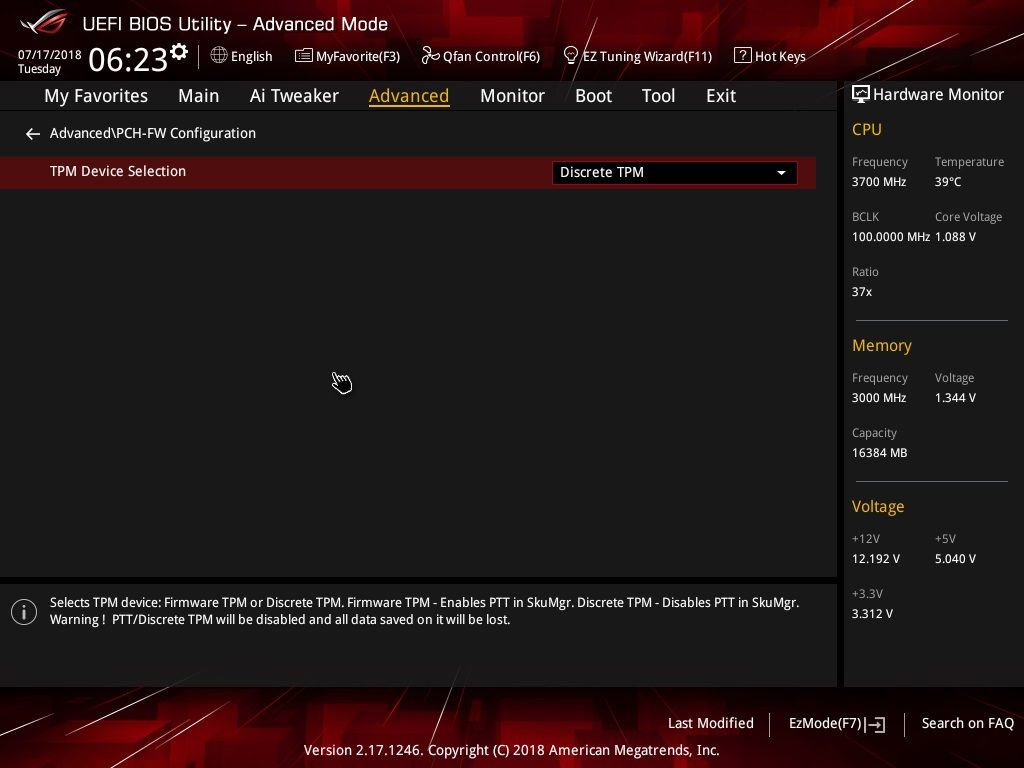
Right next to the addressable header is a TPM connector (14-1 pin). TPM stands for Trusted Platform Module which securely stores keys, digital certificates, passwords, and data which is helpful in enhanced security, system integrity, protecting digital identities, etc. Next, is 10-1 pin Com connector. Connect the serial port module cable to this connector if using any. Backward compatibility is always welcome. Next is 10-1 AAFP front panel audio connector. This connector is for the chassis-mounted front panel audio ports with HD Audio.
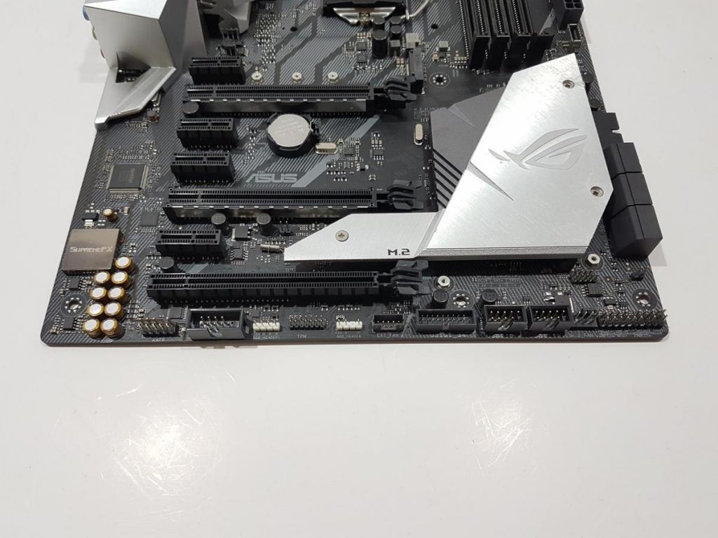
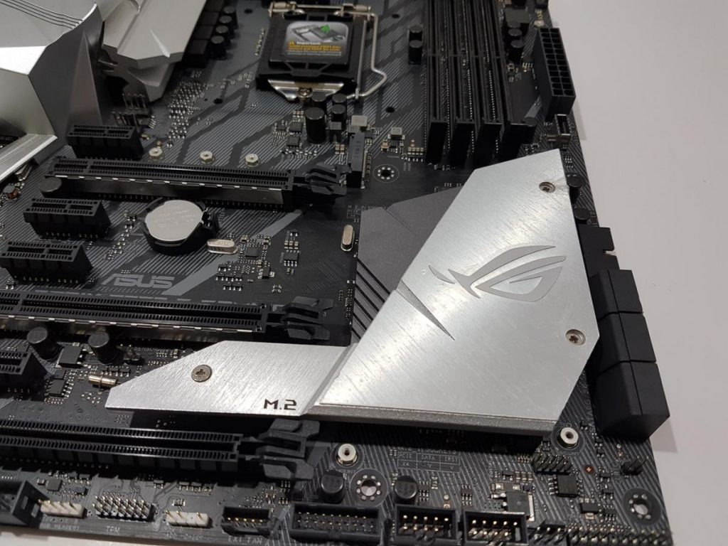
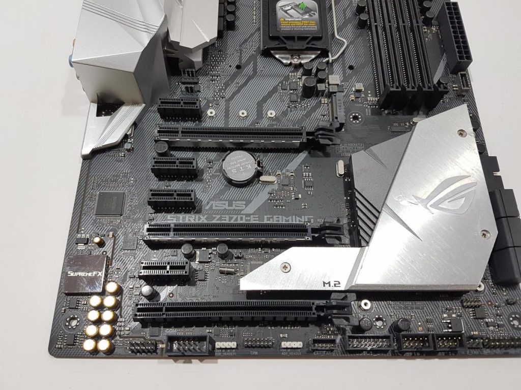
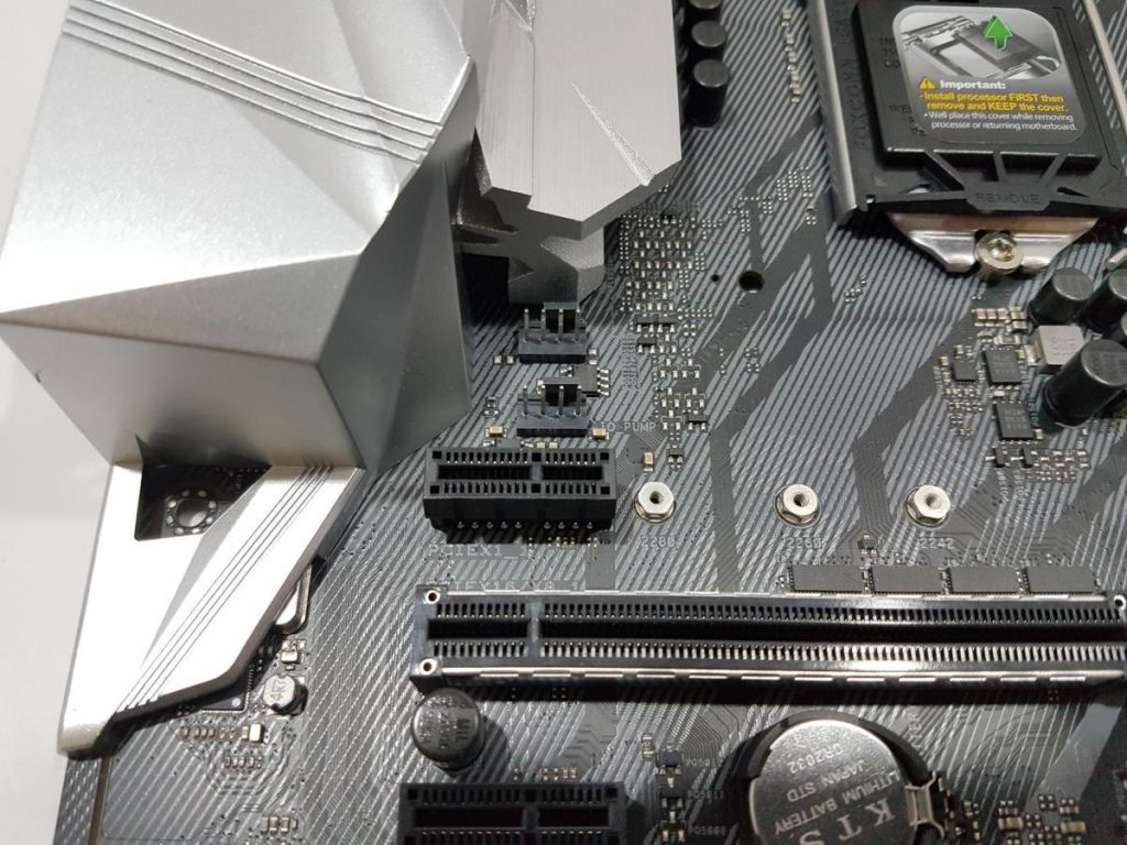
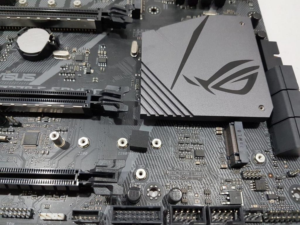
Let’s take a look at the M.2 storage options on this motherboard. One M.2 socket is located right below the CPU socket facing the first PCIe slot. It is referred to as M.2_2 and it supports PCIe 3.0 x4 M key design and types 2242/2260/2280 PCIe storage devices. It does not have any heatsink cover.
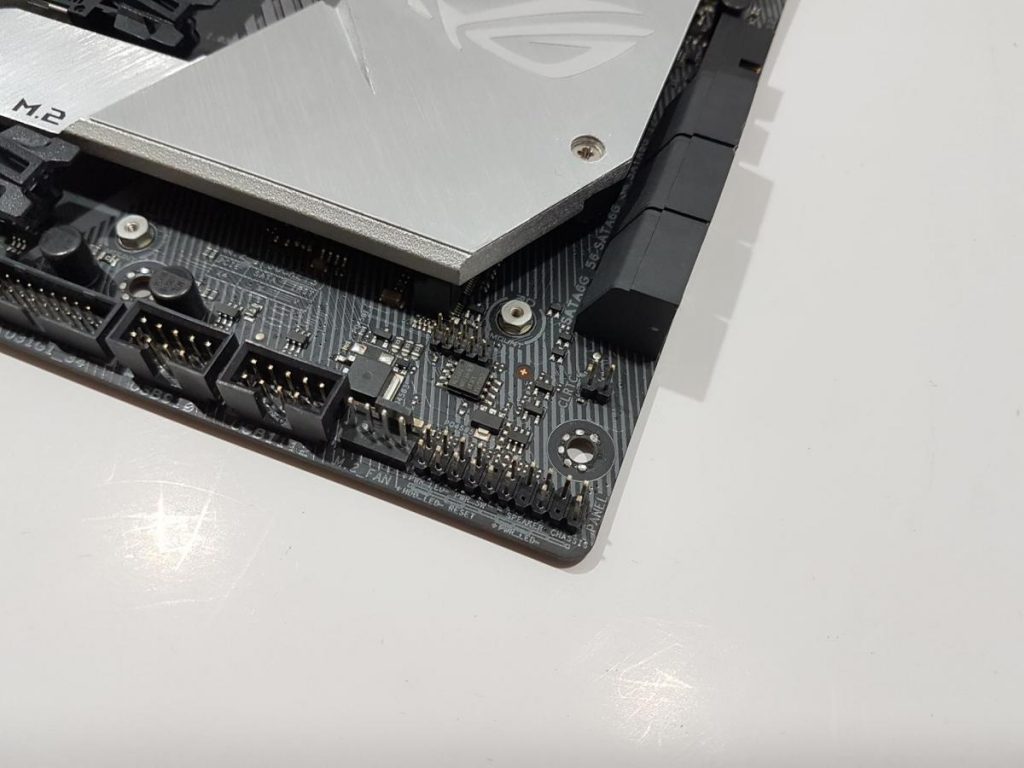
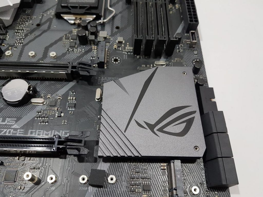
The second M.2 socket is right under the Chipset cover. This cover is actually a heatsink cover and can be taken off by removing 3 screws. M.2 is printed on the arm extending between the PCIe slots. Taking it off will show the socket. This socket is referred to as M.2_1 and it supports PCIe 3.0 x4 and SATA mode M Key design and types 2242/2260/2280 PCIe and SATA storage devices.
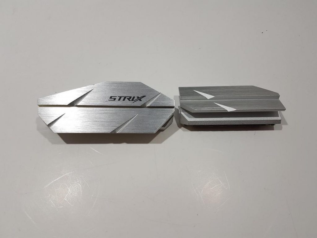
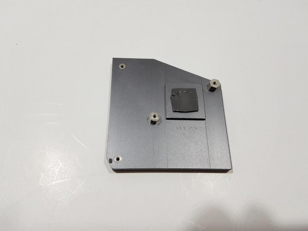
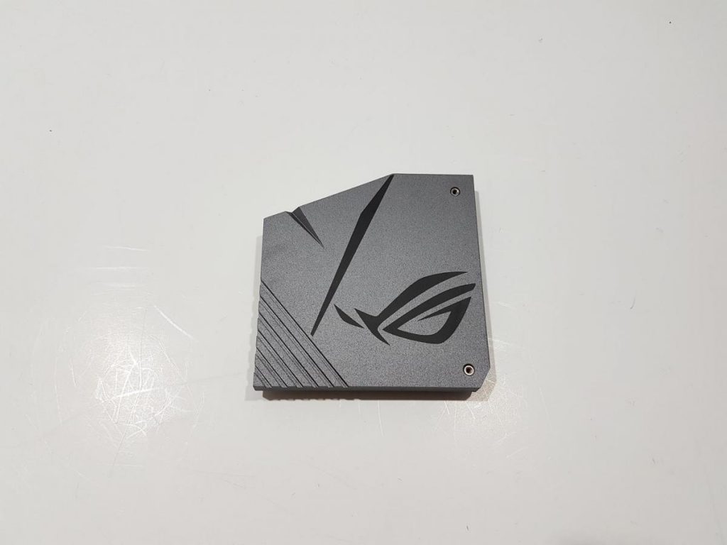
Both of these sockets support Intel Rapid Storage Technology (IRST). The M.2_1 has a heatsink cover. A protocol support table is printed right on the PCB for this socket. There is a thermal pad pasted to the underside of the heatsink. The other side of the pad is covered with a protective sheet that the user can take off before mounting the heatsink onto the M.2 device. This heatsink has a ROG eye pasted on its top side. There is no LED underneath to light it up. The chipset heatsink also has a ROG eye and some angled lines for pure aesthetics. There is a gray color pad on the underside of the heatsink making contact with the chip.
Let’s take a look at the PCIe slots. This board has a total of 7 PCIe slots. Slots no 1, 3, 4, and 6 from the top are PCIe Gen 3.0/2.0 x1. The second slot is PCIe Gen 3.0/2.0 x16. This slot is electrically x16 implemented and connected to the CPU. This is the only slot with x16 speed on the board. The fifth slot is PCIe Gen 3.0/2.0 x8. The seventh slot is PCIe Gen 3.0/2.0 x4 and is taking PCIe lanes from the chipset. Please note that in the case of two-way SLI or CF-X, slots no 2 and 5 will operate at x8/x8 speeds.
These slots have been designated as: –
| Slot No | Description |
| 1 | PCIEX1_1 |
| 2 | PCIEX16/x8_1 |
| 3 | PCIEX1_2 |
| 4 | PCIEX1_3 |
| 5 | PCIEX8_2 |
| 6 | PCIEX1_4 |
| 7 | PCIEX4 |
There is a CMOS battery right below the second PCIe slot. The second and fifth PCIe slots are Safeslots. Featuring a new single-step, insert molding, and manufacturing process that integrates fortifying metal and additional solder points, Safeslot provides stronger PCIe device retention (1.6X) and greater shearing resistance (1.8X).
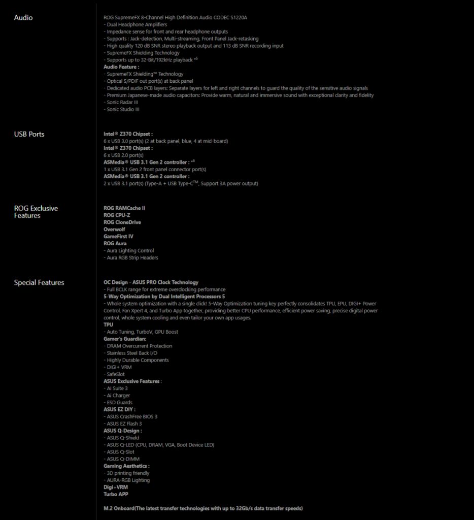
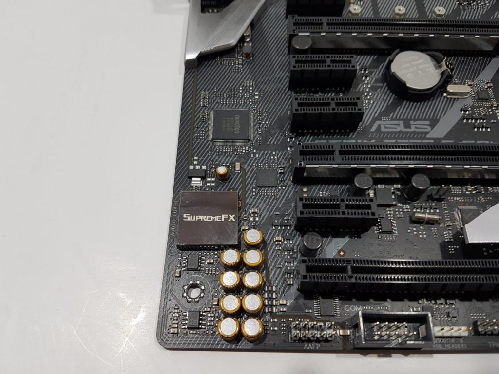
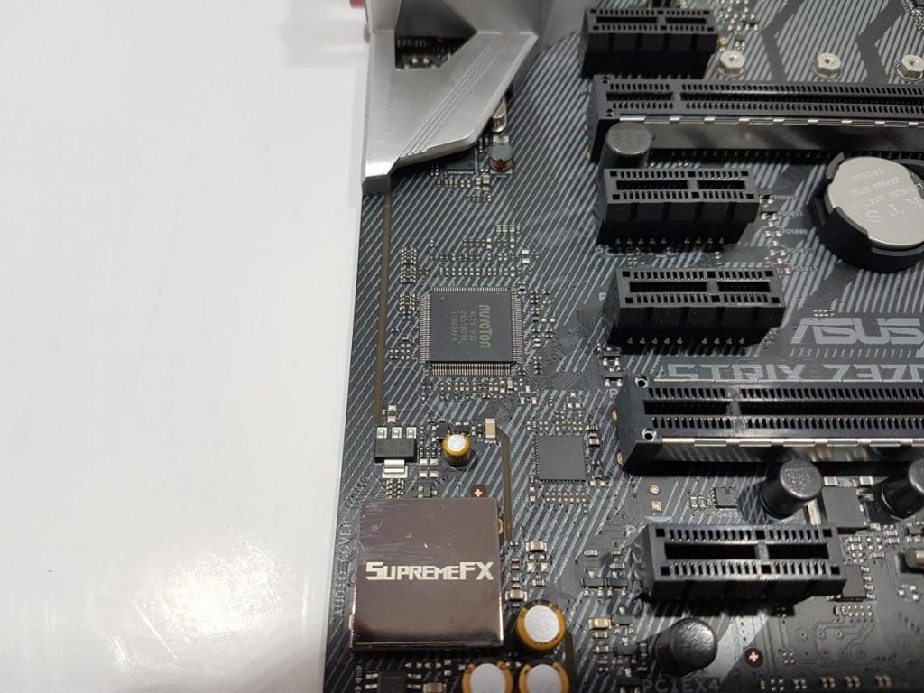
Now, it is time to look at the Audio solution on this board. SupremeFX is the name of the onboard Audio solution from Asus on their ROG lineup of motherboards. Asus has added a low-dropout regulator for cleaner power delivery to the SupremeFX S1220A codec, an ESS® Sabre Hi-Fi ES9023P digital-to-analog converter for superior front-panel output, and a Texas Instruments® RC4580 and Opa 1688 op-amps for high gain with low distortion — which all adds up to audio that envelops you as never before.
Using SupremeFX S1220A, we’ve 10 DAC Channels, simultaneous 7.1 channel playback, independent 2.0 channel, and multiple-stream stereo to front-panel outputs. Delivering all this power are Nichicon capacitors with high-precision clock sources and switching Mosfets. We’ve RC 4580 buffer which provides excellent voltage and current for perfect true-to-life tonality and sound imaging.
Hardware is backed up by the comprehensive software suite in the form of Sonic Suite III and Sonic Radar III. This software allows the user to custom tailors the sound according to their needs with later software helping the users in identifying the position of the enemy while gaming.
The Audio hardware has been implemented on the lower left side of the PCB and it has audio line shielding to block electromagnetic interference from the motherboard to provide a clean audio signal. Asus is using multiple layers on the PCB for the audio hardware. S1220A with the letter A designates Asus exclusive chip implementation and it has a 113 dB signal-to-noise ratio on the in-line connection and 120dB on the out-line connection.
This motherboard has the following USB ports:
- Intel® Z370 Chipset: 6 x USB 3.0 port(s) (2 at back panel, blue, 4 at mid-board)
- Intel® Z370 Chipset: 6 x USB 2.0 port(s)
- ASMedia® USB 3.1 Gen 2 controller: 1 x USB 3.1 Gen 2 front panel connector port(s)
- ASMedia® USB 3.1 Gen 2 controller: 2 x USB 3.1 port(s) (Type-A + USB Type-CTM, Support 3A power output)
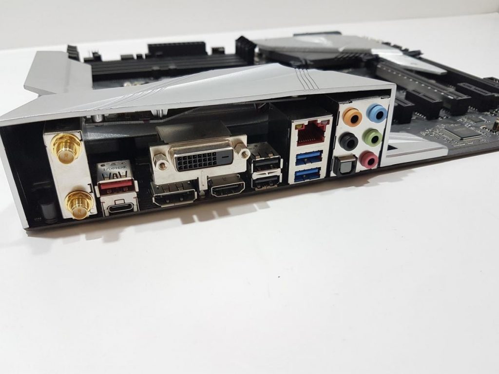
Let’s take a look at the rear I/O panel of the motherboard. The following connectivity options are there:
- 1 x DVI-D
- 1 x DisplayPort
- 1 x HDMI
- 1 x LAN (RJ45) port(s)
- 2 x USB 3.1 Gen 2 Type-A + USB Type-CTM,
- 2 x USB 3.1 Gen 1 (blue) ,
- 2 x USB 2.0
- 1 x Optical S/PDIF out
- 5 x Audio jack(s)
- 1 x ASUS Wi-Fi GO! module (Wi-Fi 802.11 a/b/g/n/ac and Bluetooth v4.2)
Asus ROG Strix Z370-E Gaming features the very latest Intel® Ethernet (I219-V) for faster, smoother gaming. Intel’s LAN has the serious double advantage of reducing CPU overhead and offering exceptionally high TCP and UDP throughput. Asus has implemented LANGaurd. This helps to ensure safer, more reliable connections for your gaming sessions.
Advanced signal-coupling technology and premium surface-mounting processes join forces to protect the motherboard’s connection, plus electrostatically guarded and surge-protected components (ESD Guards) for 1.9x greater tolerance to static electricity and 2.5x greater protection (up to 15kV) against surges.
In addition to the Intel Ethernet, Asus has implemented next-level 802.11 a/b/g/n/ac (Wi-Fi with 2×2 dual-band 2.4/5GHz antennas for up to 867 Mbps* transfer speeds — and the very latest Multi-User Multiple In Multiple Out (MU-MIMO) technologies to ensure that every connected user experiences the best wireless and online speeds.
Backing all this up is the GameFirst application which optimizes network traffic for faster, lag-free online gaming — and now it supports Multi-Gate Teaming to team up to 4 networks for maximum bandwidth and smooth gameplay. Intelligent mode automatically compiles a database by parsing new app data to ensure that every game is optimized for the best performance. In addition to that, Asus has provided support for Bluetooth v 4.2.
Controllers, Digi+, OC Design
A dedicated base clock (BCLK) generator has been implemented that extends CPU and memory overclocking margins. This custom solution works in tandem with the TPU to enhance voltage and base-clock overclocking control, providing the flexibility to extract every ounce of performance from 8th Generation Intel® processors.
With support for DDR4 memory users are able to drive memory frequencies to 4000MHz (and beyond when overclocked)! ASUS-exclusive T-Topology circuit design plus OC Socket provides the superb memory-overclocking capability to unleash the full power of DDR4 by minimizing coupling noise and signal reflection.
With innovative equidistant memory channels, it delivers the most balanced control and powerful overclocking compatibility. Driving the main I/O and monitoring operations is the Nuvoton NCT 6793D chip. The NCT6793D is a member of Nuvoton’s Super I/O series capable of monitoring critical parameters in PC hardware including power supply voltages, fan speeds, and temperatures. It supports both high-accuracy current mode sensing and low-cost thermistor mode sensing and also supports the Nuvoton SMART FAN™ I and SMART FAN™ IV algorithms for fan speed control. It also supports the power fault alert function, which protects the system while the input voltages are abnormal. This works in tandem with the STM32F072 microcontroller chip.
We have ASMedia ASM3142 and ASM1480 chips on the board. USB 3.1 ports are being controlled using the ASMedia controller whereas the onboard USB 2.0 and 3.0 ports are being controlled from the Intel Z370 chipset. The TPU chip being used is the same as we saw on many other
Asus motherboards and it is KB3720Q which is used to automate some of the overclocking functions of the motherboard. Asus has been using Digi+ technology for quite some time. Asus Strix Z370-E is equipped with ASUS Digi+ Power Control for maxed-out overclocking potential, enhanced system stability, and superb power efficiency. Digi+ Power Control is the industry’s leading digital power controller (ASP1400BT A1731AS) and it’s fully compliant with Intel’s IMVP8 specifications, for smoother, safer power.
We have a PWM controller handling 10 power phases. There are 8+2 Power phases on this motherboard. We’ve more than adequate phases for stable power delivery to the motherboard and various components. This also helps in stable overclocking.
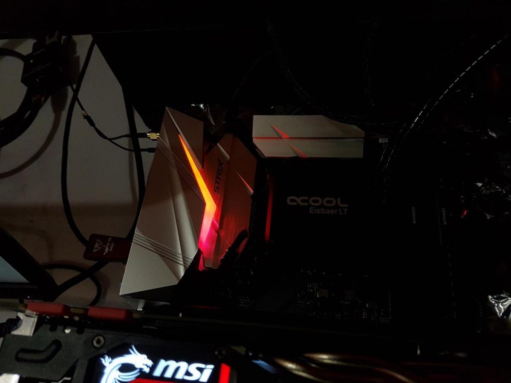
Here are some pictures of the LED Lighting on the motherboard.
Testing System
The motherboard was tested using the following test bench setup:- Intel i7 8700k Motherboard
- Asus ROG Strix Z370-E Gaming
- MSI GTX 1080 8G Gaming X
- Corsair Vengeance LPX 2x8GB @ 3000MHz
- Alphacool Eisbaer 360 LT
- Hyper X 120GB SSD
- Samsung 840 EVO 1TB [Steam Games]
- Western Digital 6TB Black HDD
- Corsair CX850M PSU
Microsoft Windows 10 x64 Pro was used for all the testing. Nvidia 398.36 drivers were used for graphics card testing. The following software was used for performance evaluation: –
Storage Drive Tests:
- AS SSD
- ATTO
- Crystal Disk Mark
CPU Tests:
- Cinebench R15
- GeekBench 4.0.3
- 7-Zip
- Fritz Chess
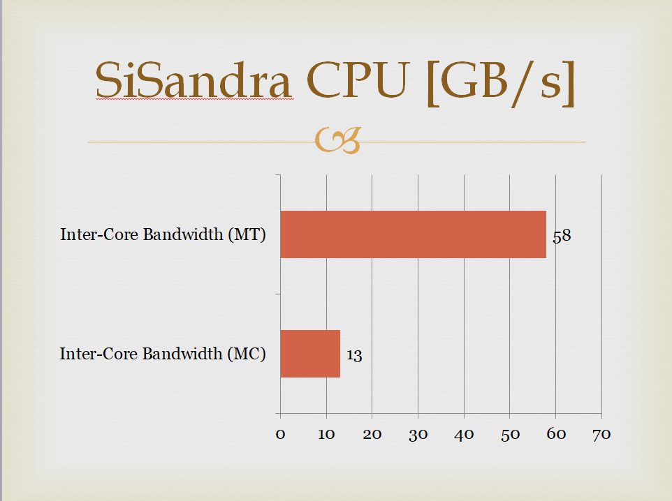
- SiSandra CPU
- AIDA64
- Super Pi
Memory Tests:
- AIDA64 Extreme
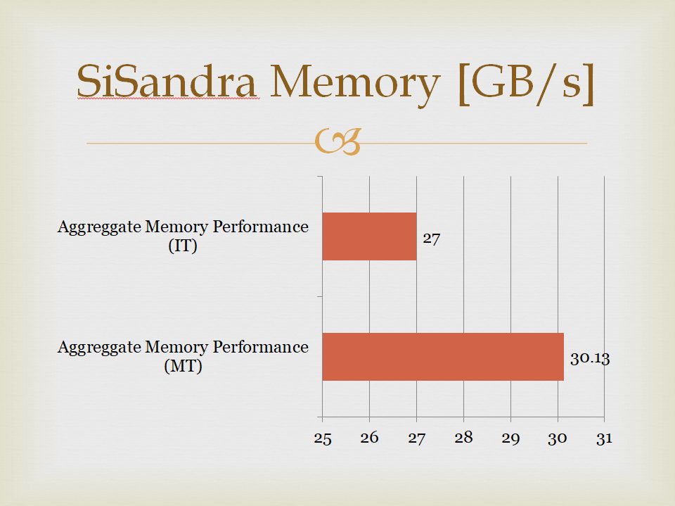
- SiSandra Memory
Overall System Tests:
- PCMark
- Performance Test
For gaming and synthetic bench of the graphics card the following software were used:-
- 3DMark
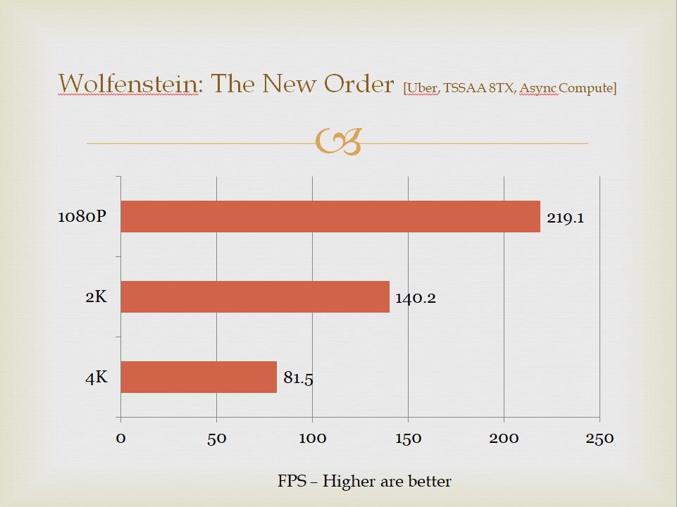
- Wolfenstein The New Order
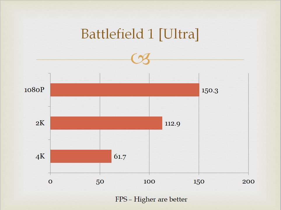
- Battlefield 1
- Metro Last Light Redux
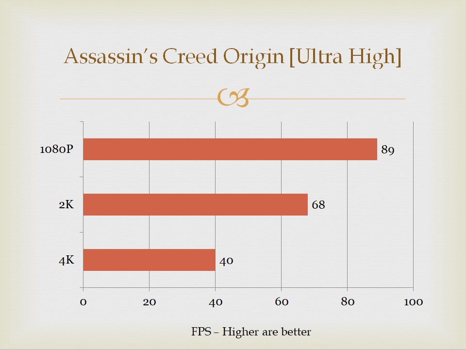
- Assassin’s Creed Origin
BIOS
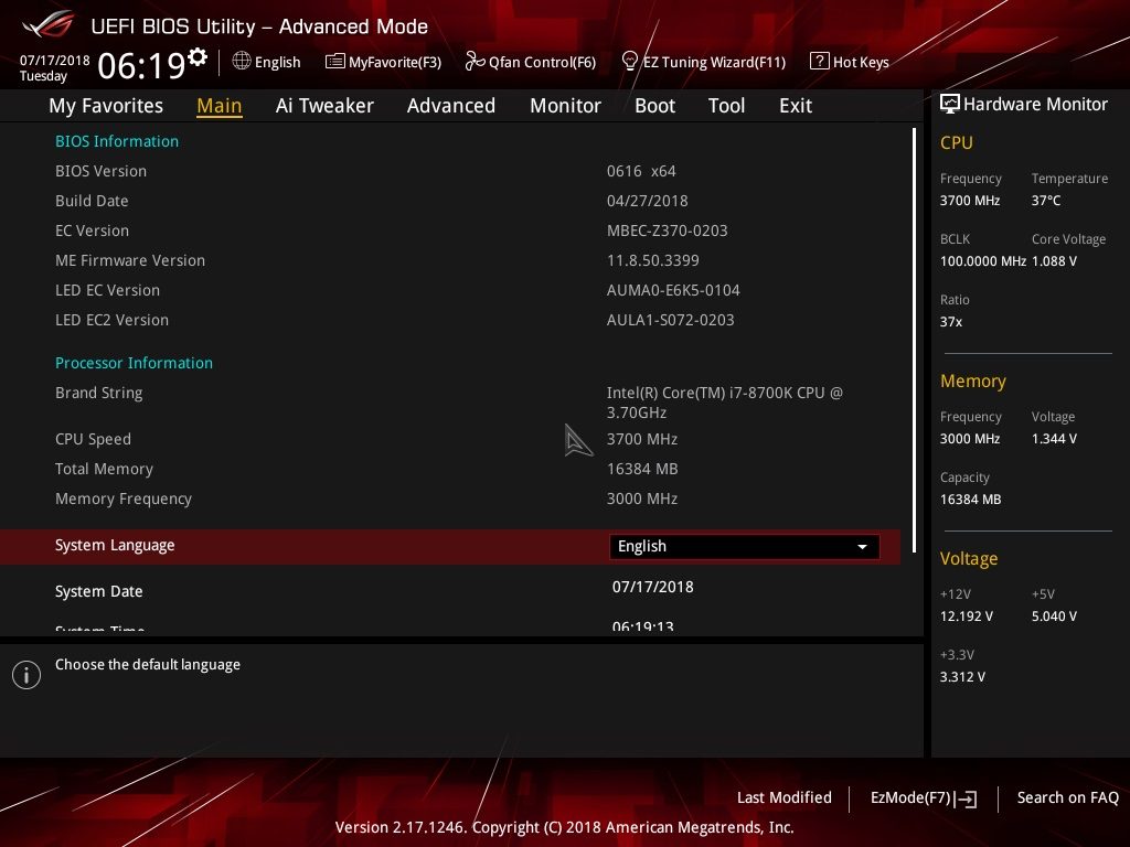
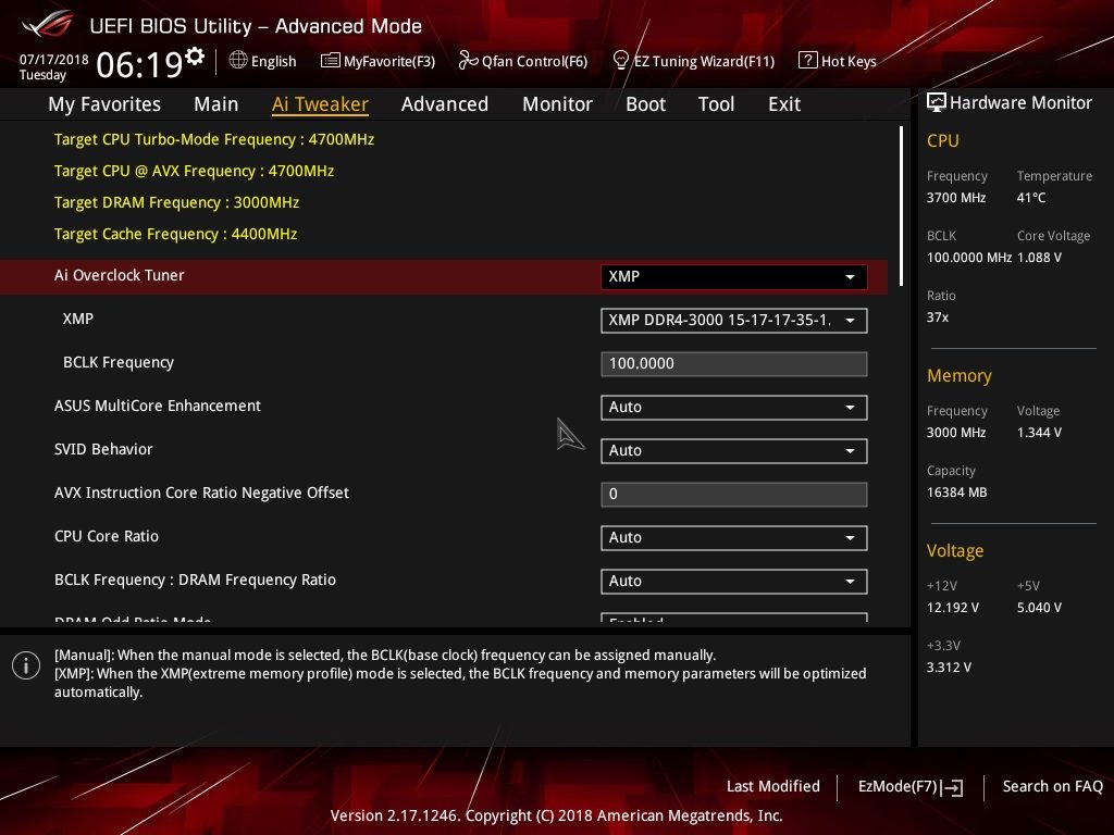
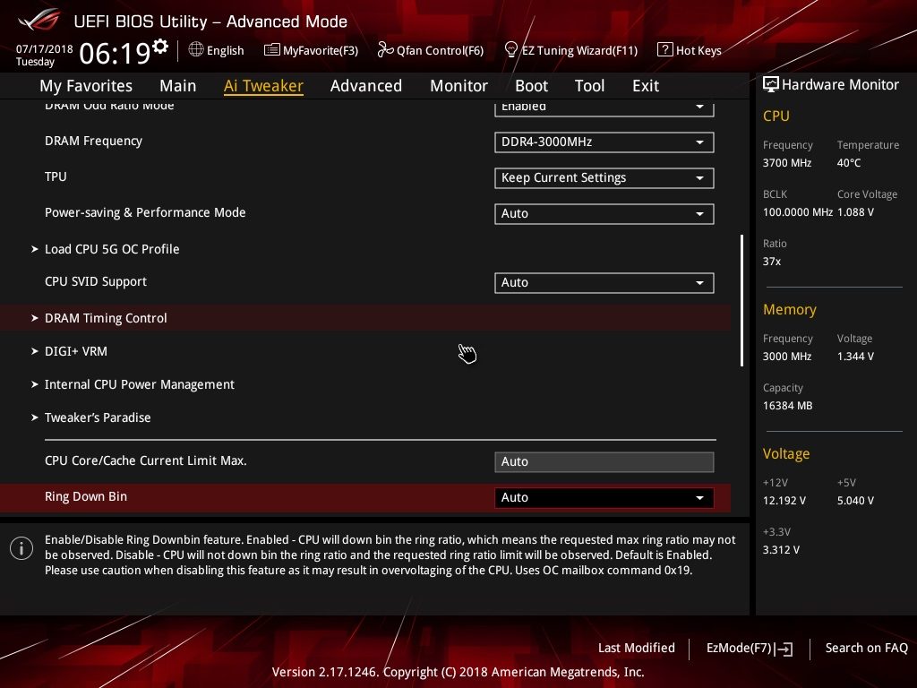
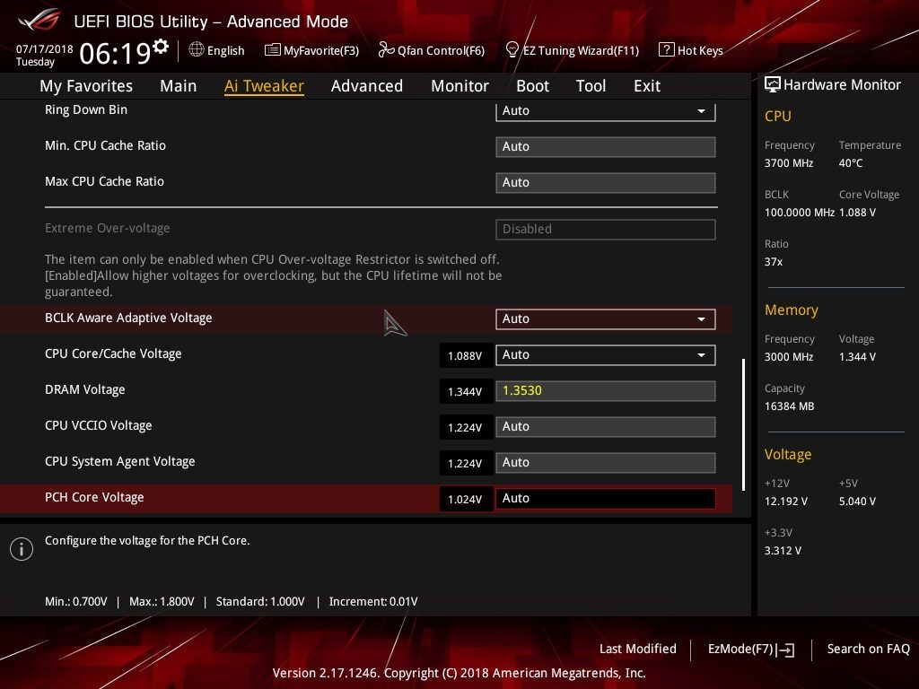
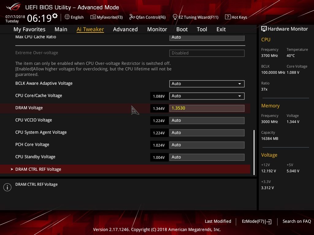
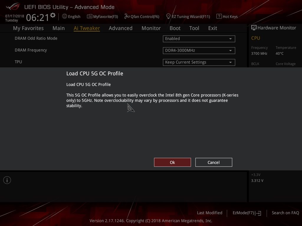
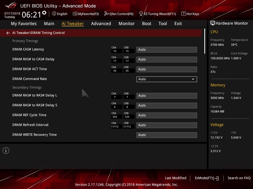
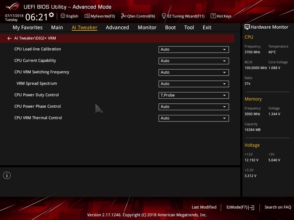
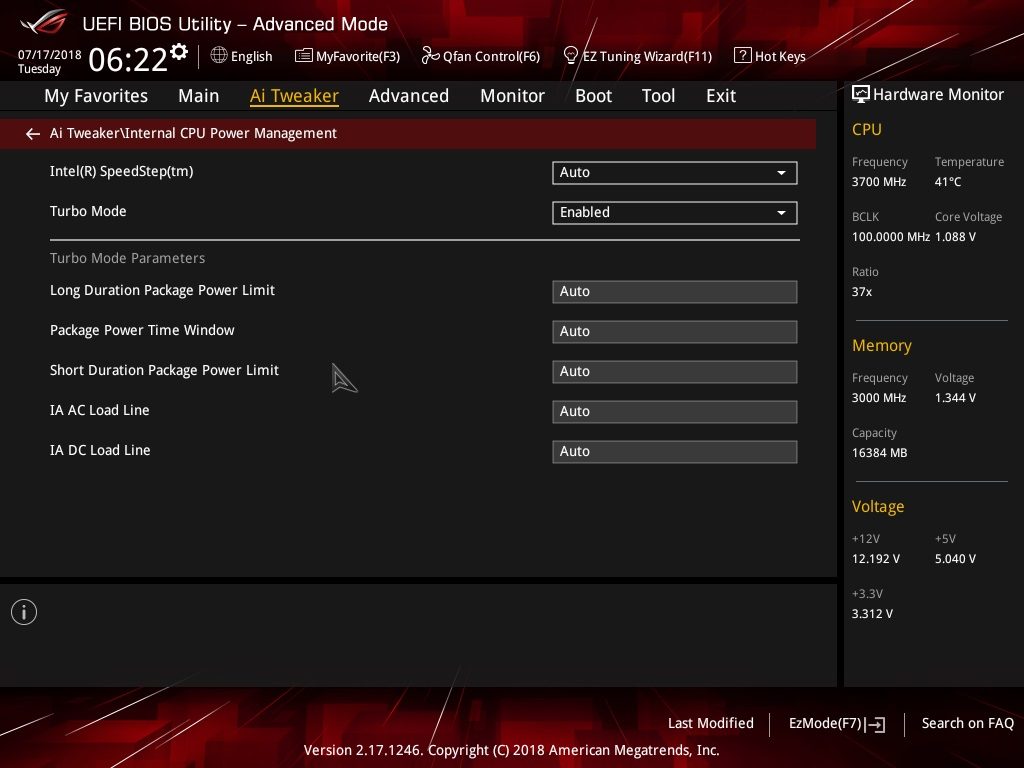
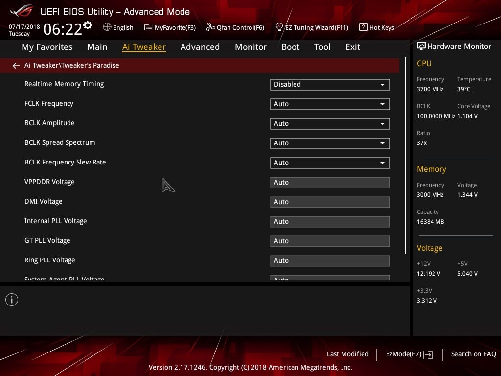
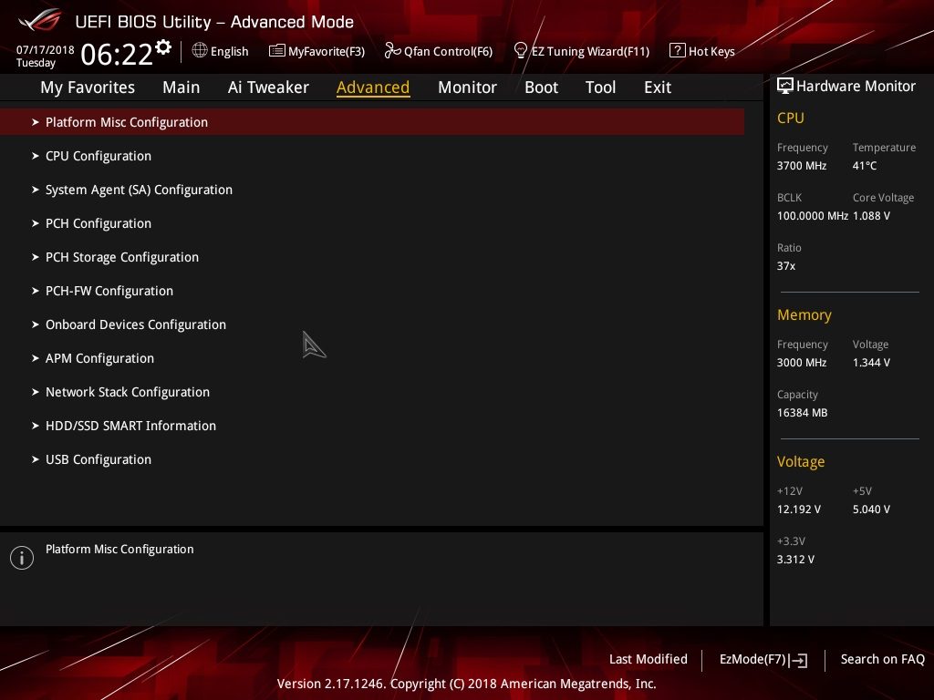
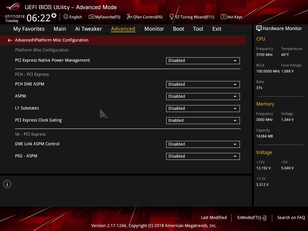
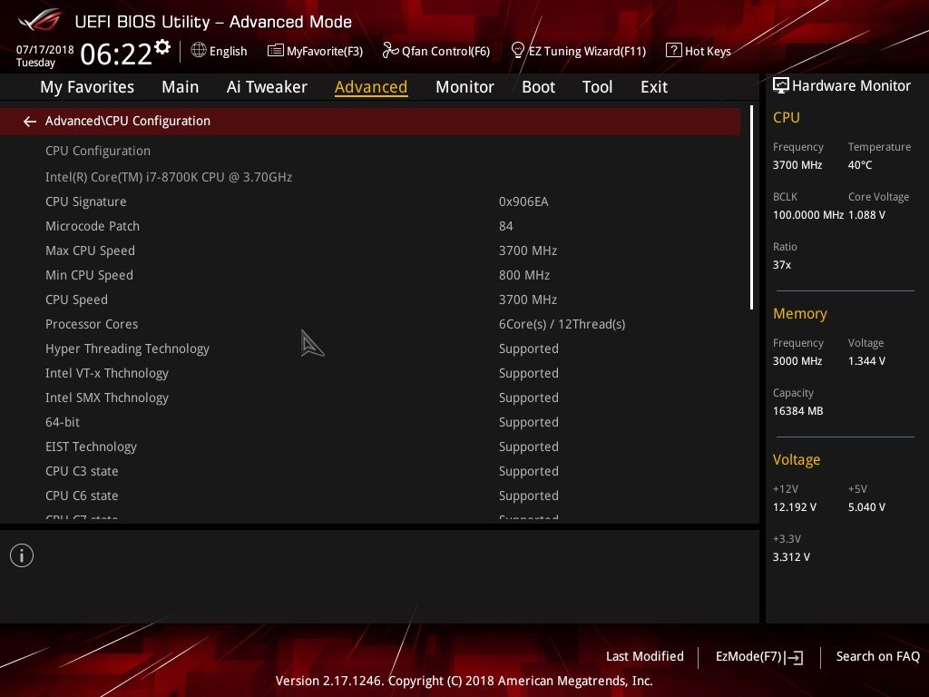
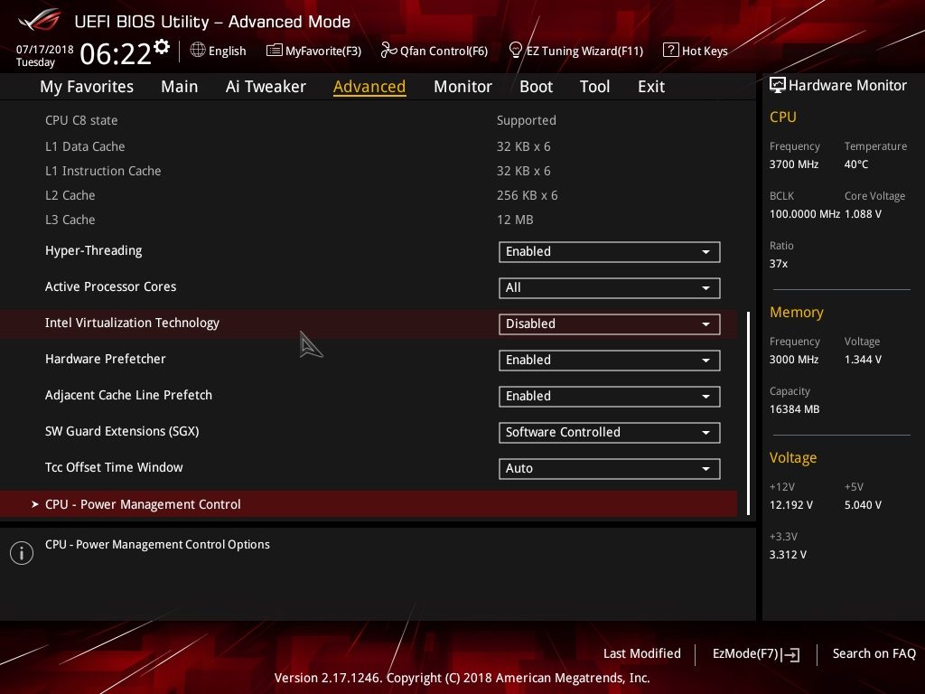
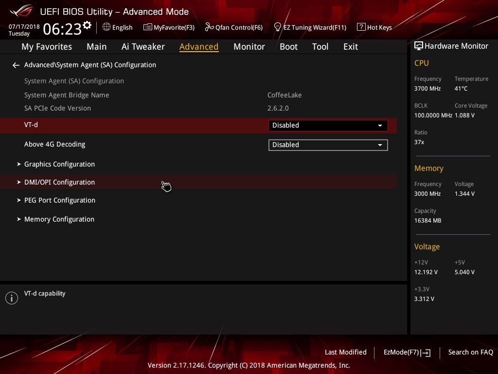
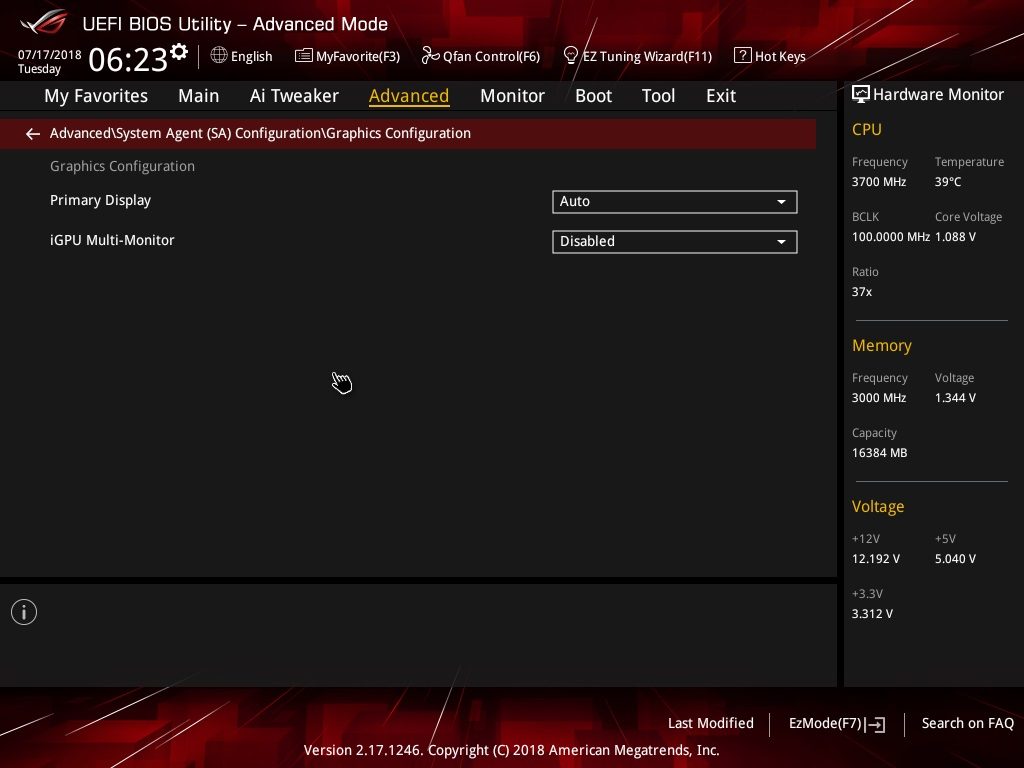
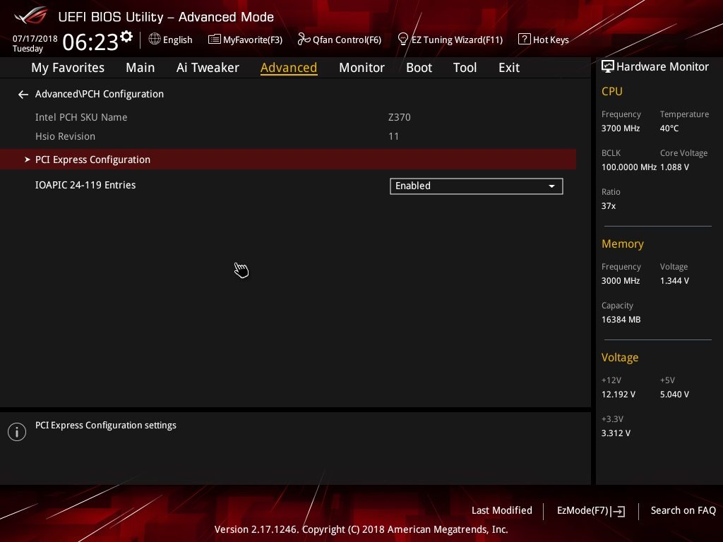
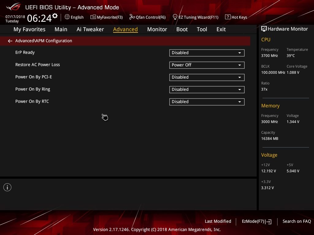
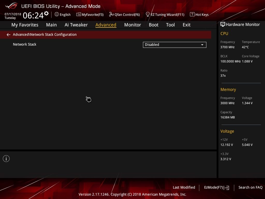
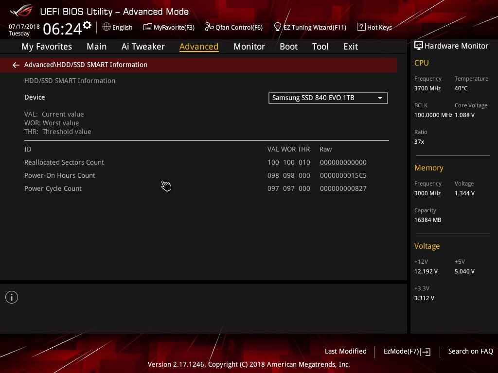
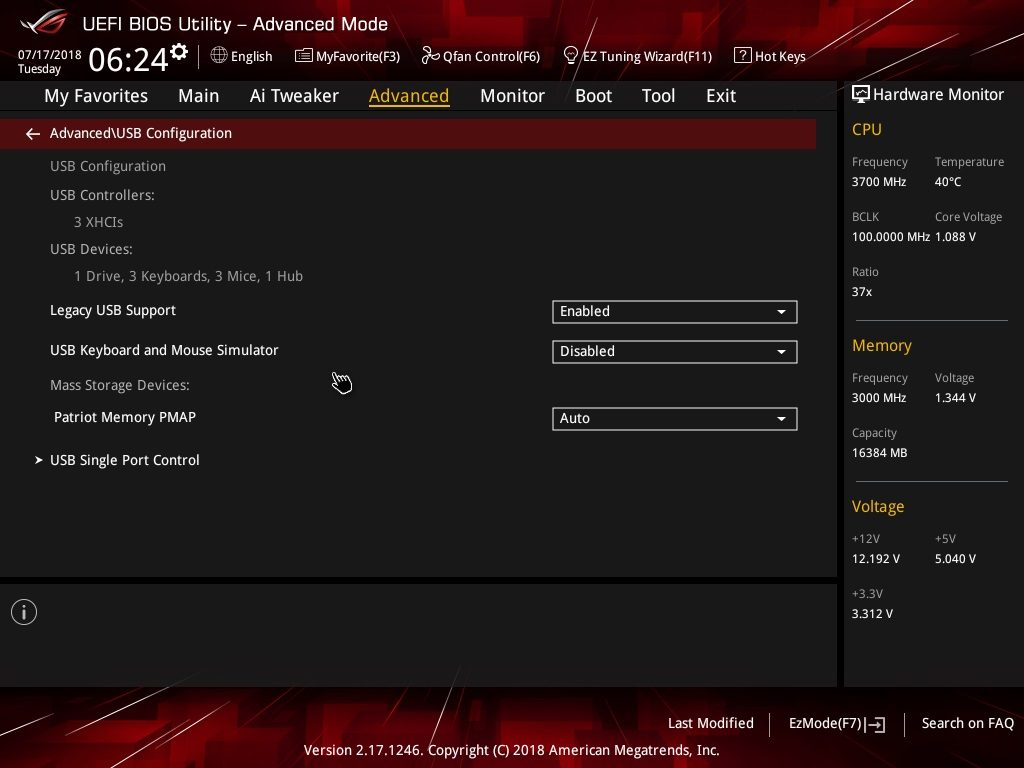
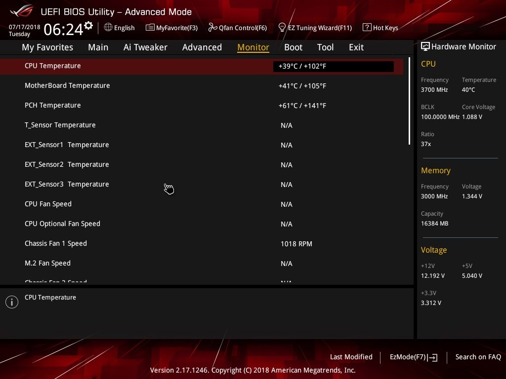
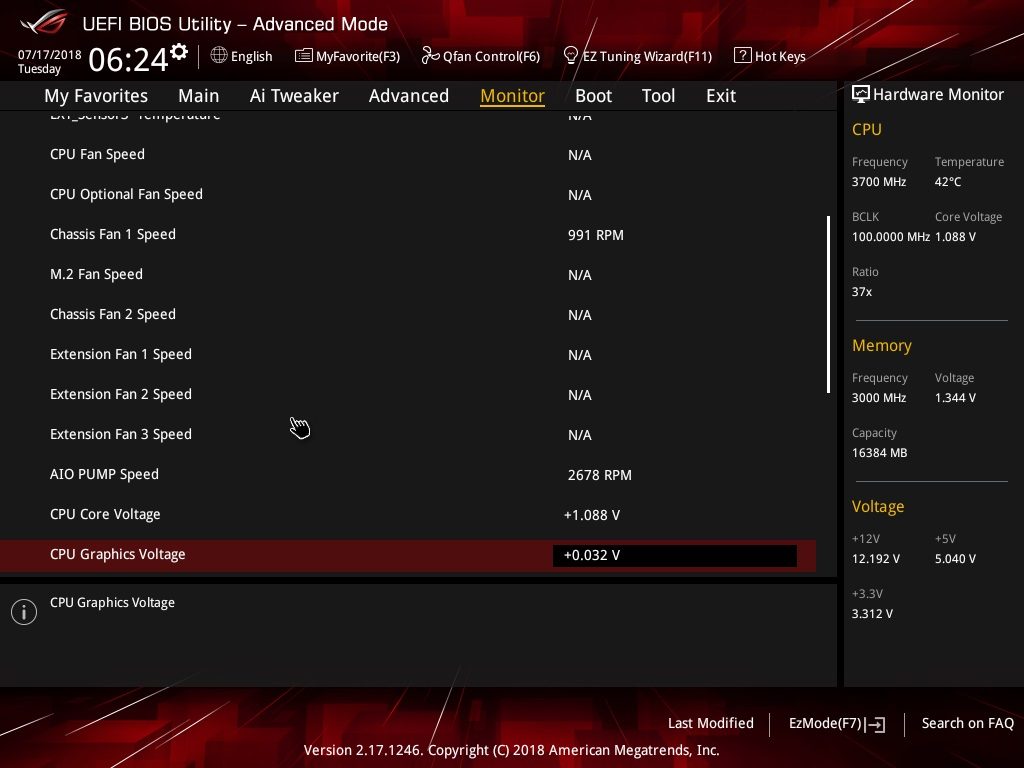
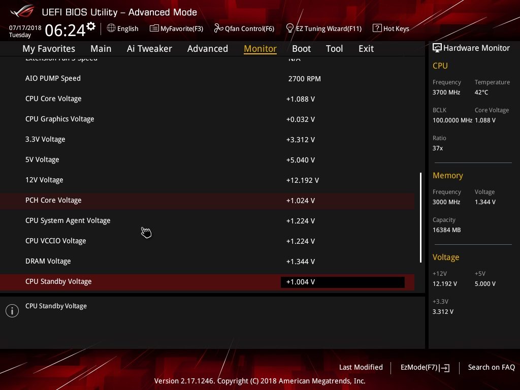
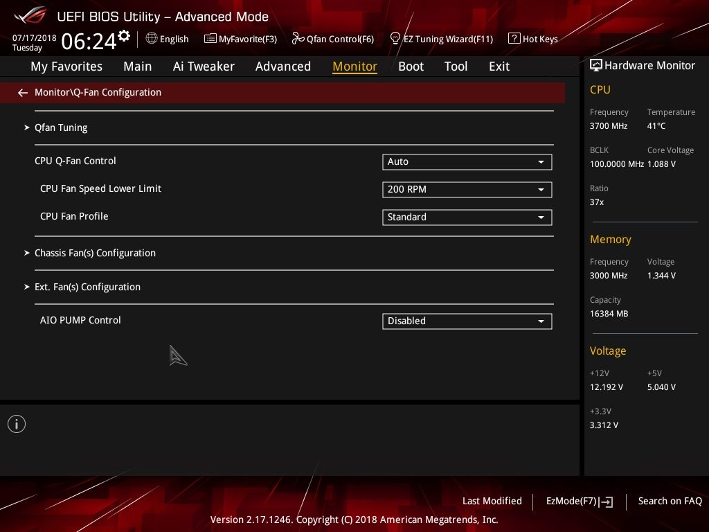
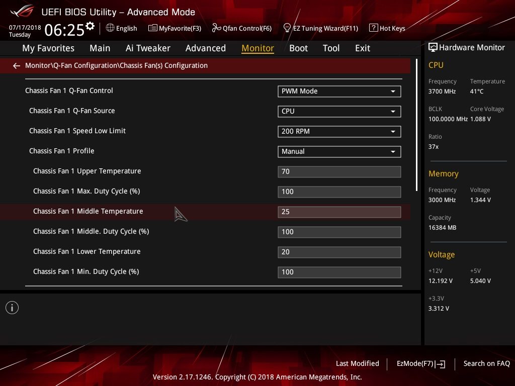
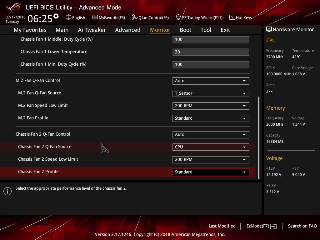
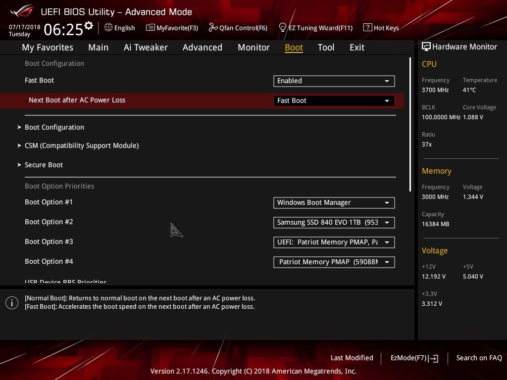
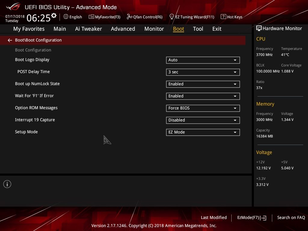
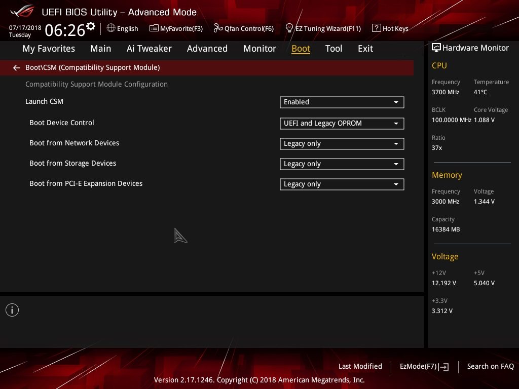
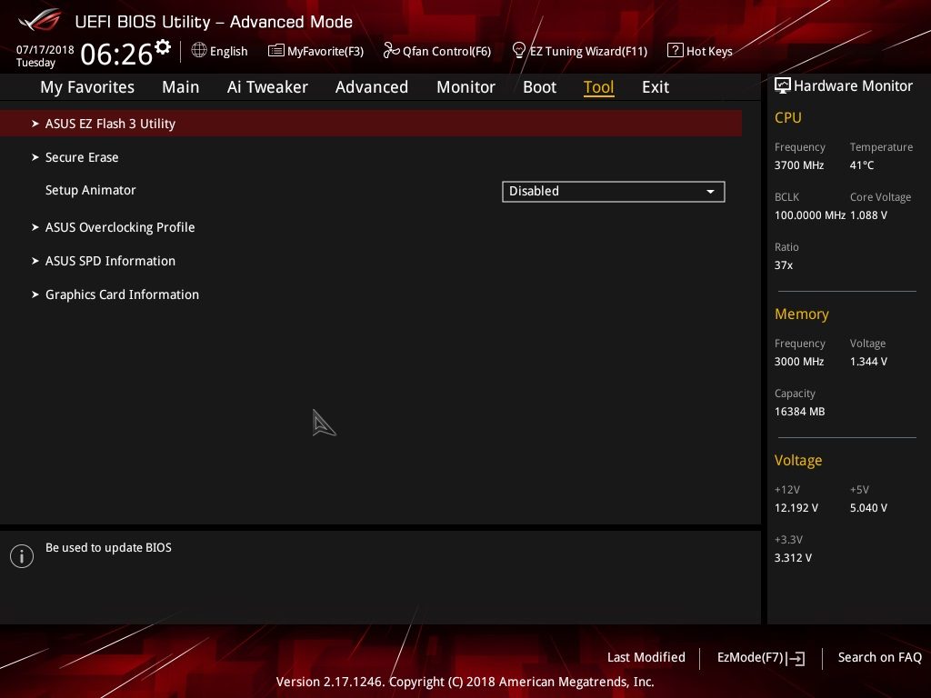
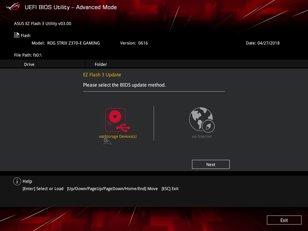
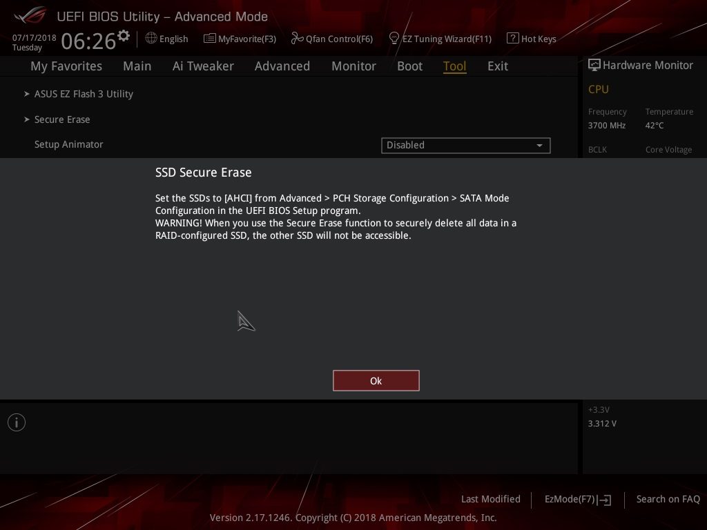
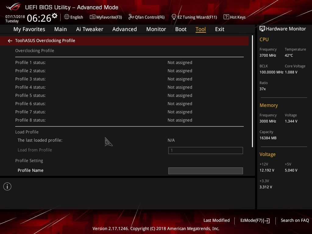
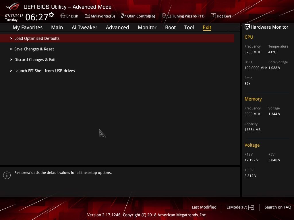
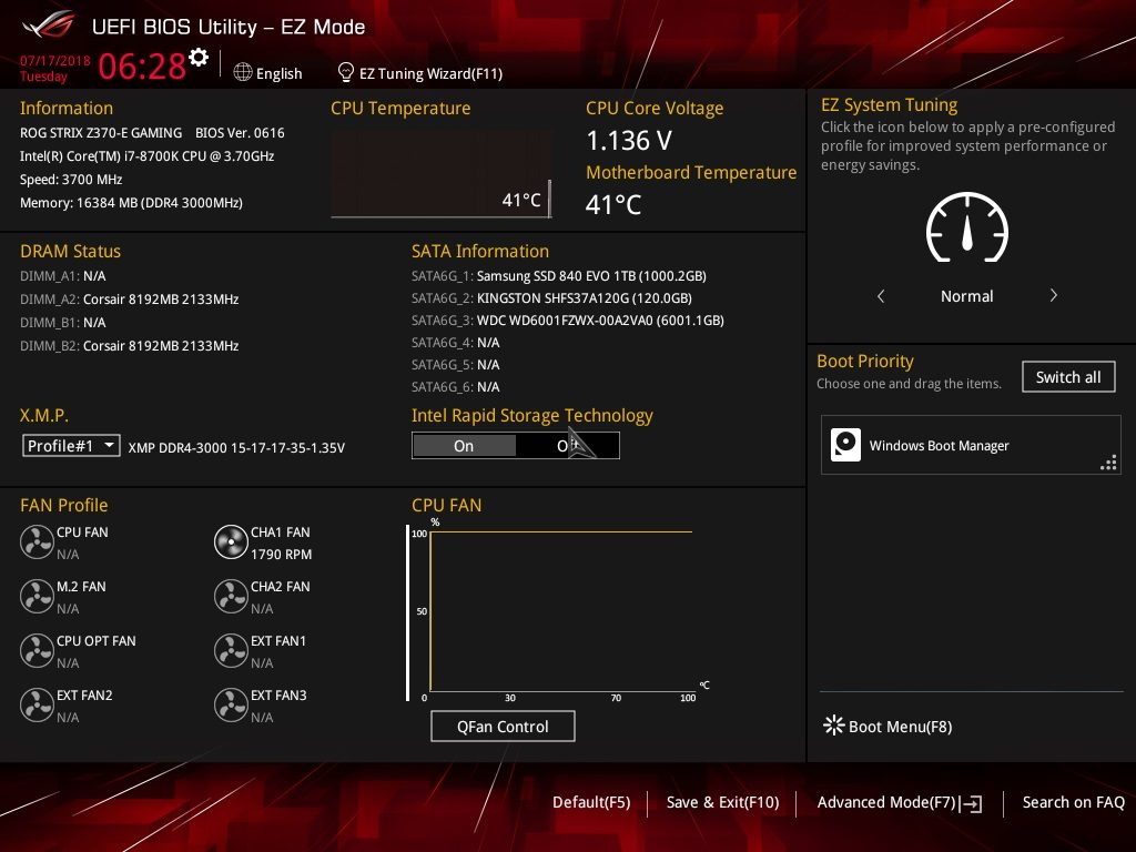
Before discussing the performance of the test build, let’s have a look at the BIOS of the Maximus X Hero. Asus has provided a ton of options in their media-acclaimed UEFI BIOS. The graphical interface is easy to navigate through using the mouse and the keyboard. When loaded, EZ Mode will be enabled. This mode is for the new users. For experienced users, pressing F7 would load Advanced Mode. Extreme Tweaker Menu is loaded on the BIOS startup. It shows the CPU and Memory related critical info like Temps, Clocks, Ratio etc on the right side. On the left side, we’ve to overclock related options. XMP can be loaded from the Ai Overclocker Tuner option. The main page is for information only showing the system date and time, BIOS version, CPU information etc. AiTweaker menu has all the CPU and Memory related settings and what not. AiOverclock Tuner has Auto, Manual and XMP settings. Experienced users will tend to use the manual option to better tune their overclocking attempts. XMP will load the XMP profile of the connected DRAM for its effective speed. Once loaded, the XMP profile information will be visible against XMP. Asus has implemented their own algorithms to enhance the performance of the CPU named as Asus MultiCore Enhancement. DRAM Frequency will be automatically shown to the correct one once XMP is loaded. User can select the frequency from the given list when manually overclocking the DRAM. DRAM Timing Control will let the user to set and control the DRAM timings according to their need. Load CPU 5G OC Profile is something new with this motherboard. It will automatically try to overclock the CPU to 5.0GHz using the pre-defined algorithm and settings. Please, note that 5GHz is not guaranteed. It varies from chip to chip being the silicon difference and it may supply extra voltage to the CPU which would result in more thermal heat. There is a single setting to control the CPU Cache/Core Voltage. CPU Load Line Caliberation and other related settings are in the Digi+ VRM sub-section. Settings like SpeedStep and Turbo Mode can be accessed in the sub-section named Internal CPU Power Management. Tweaker’s Paradise is for advanced users and should not be disturbed unless you know what you are doing. Advanced menu has all other options related to CPU Management, System Agent Configuration, PCH and PCH Storage related options, After Power Management options, USB settings, On-Board devices settings, etc. If you want to control the Hyper threading, no of active cores etc features of the CPU, you can find them under the CPU Configuration option. System Agent Configuration will let you set the Primary Display Adapter and other related settings. PCH settings will let you change the SATA mode and other related settings. Monitor section will let you see the current temperature of the areas with integrated thermal sensor as well T_Sensor. You can also see the RPM of the connected fans and AIO pumps as well as voltages. Chassis Fan headers can be configured independently. User can change the control type from PWM to DC to Auto. Under Boot section, you can enable/disable the Fast Boot, Boot Priority, Compatibility Support Module and other related settings. Tool menu has BIOS EZ Flash Utility 3, Secure Erase, Overclocking profile, SPD Info, Graphics Card info. There are multiple ways to update the BIOS on this board. On the back I/O port we’ve USB BIOS Flashback port. Bottom USB 2.0 port is designated for this purpose. Download the BIOS file from the Asus website. Rename it Z370EGAM.CAP. Copy that file to the root directory of the FAT32 formatted flash drive. Connect the flash drive to the designated port. Use the AZ Flash utility in the BIOS. It can even download the BIOS file from the internet and update the BIOS. Updating the BIOS is a risky process and as such should only be done when encountered any issue whose resolution is in updated BIOS. Another way of updating the BIOS is through EZ Update software when in Windows environment. Secure Erase is used to erase the SSD contents and to restore the SSD to factory default.
Main
Ai Tweaker
Advanced
Monitor
Boot
Tool
Miscellaneous
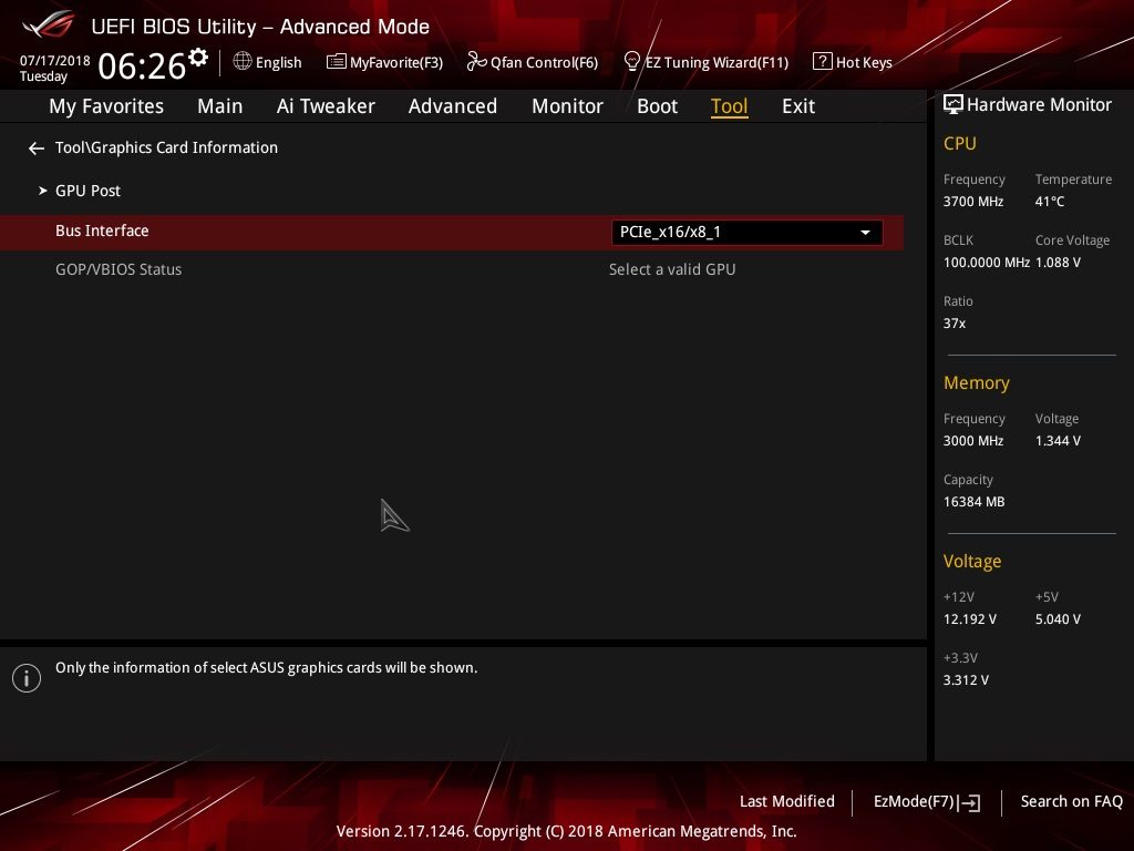
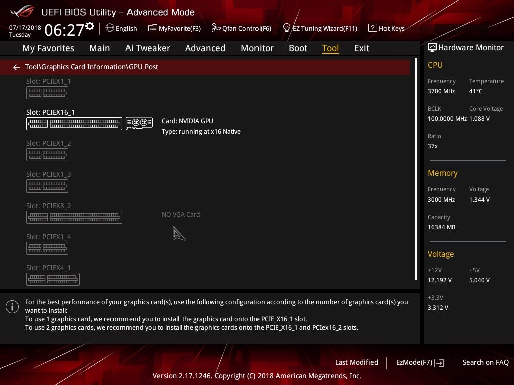
Overclocking Profile helps the user to save several profiles with different settings and to load the saved profile when needed. Up to 8 profiles can be saved. Asus SPD Information shows the DRAM info. Graphics Card Information shows the info of the installed graphics card. GPU Post will show the graphical interface of the PCIe slots with info on the installed graphics card(s). Exit Menu has related options like Exit without saving, Exit with saving, Load optimized Defaults etc. Pressing F3 will load the Favorites menu where the user can save the most frequently used settings for ease of accessing. Pressing F6 will load Q-Fan Control. The user can create custom fan curve on each fan or group of fans depending upon the implementation of fan headers on the motherboard. Pressing F7 would load the EZ Mode. EX Tuning wizard can be used to maximize the performance of the PC depending on the cooling solution being used.
Testing
This section will show the results of the various test suites and gaming benchmarks that we have run on this motherboard.
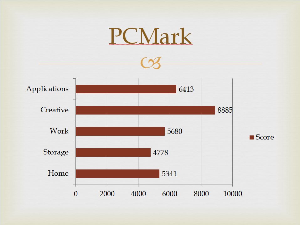
PCMark is a comprehensive application suite to measure the overall performance of the system and the storage devices. Our test build performs relatively well.
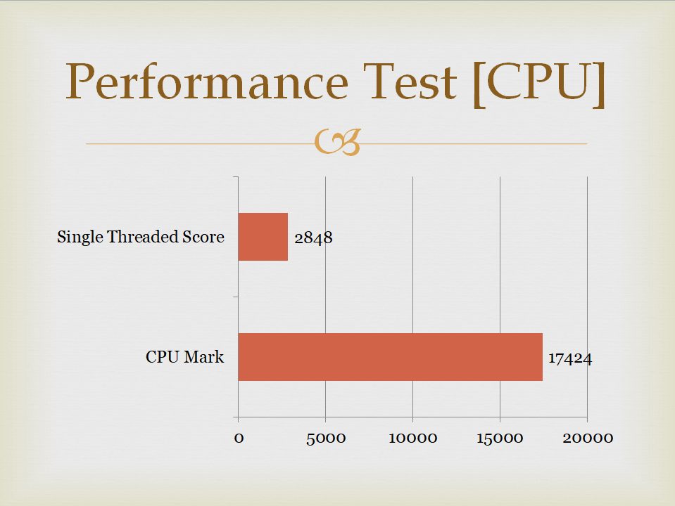
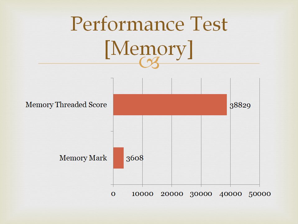
Performance Test or pTest is another comprehensive suite which measures the overall performance of the PC along with detailed tests for each component. I used it to measure the performance of the CPU and the Memory. Scores fall in 95-99% percentile which is a good indication of the performance.
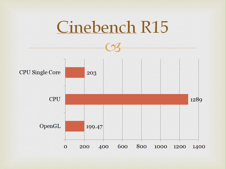
Cinebench is a real-world cross platform test suite that evaluates your computer’s performance capabilities. CINEBENCH is based on MAXON’s award-winning animation software Cinema 4D, which is used extensively by studios and production houses worldwide for 3D content creation. MAXON software has been used in blockbuster movies such as Iron Man 3, Oblivion, Life of Pi or Prometheus and much more. CINEBENCH is the perfect tool to compare CPU and graphics performance across various systems and platforms (Windows and OS X).
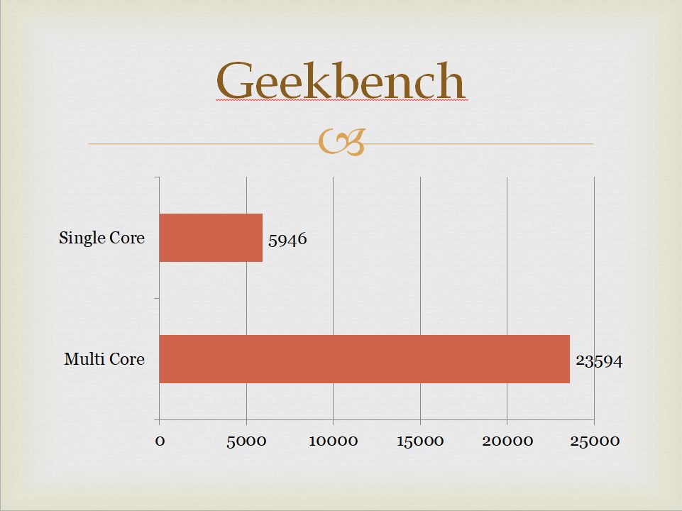
Geekbench 4 measures system’s performance across multiple platforms. Our system performs very well under this test.
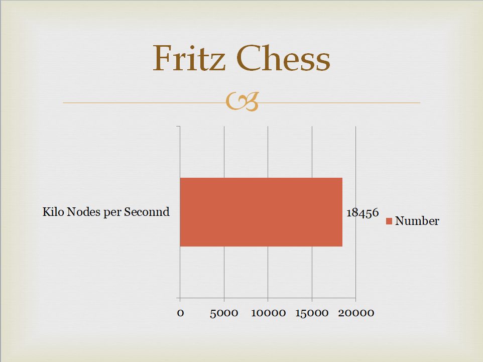
Frtiz Chess Benchmark is a CPU Performance test. It puts the CPU at 100% utilization and scales among the cores and the threads. The score is recorded as Kilo Nodes per Second and Relative speed.
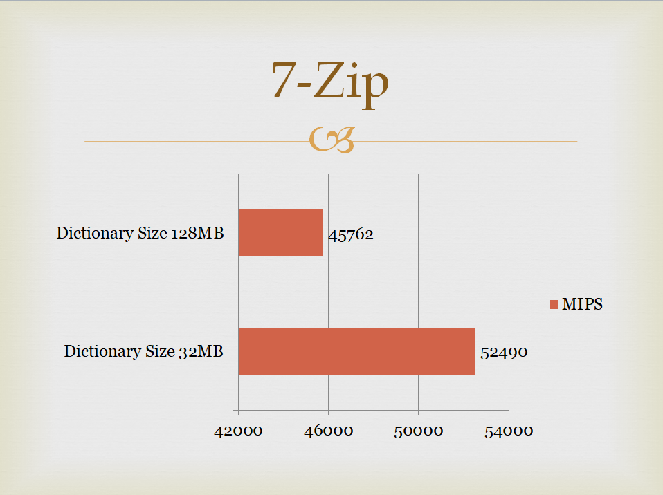
7-Zip is a compression benchmark which utilizes the Memory bandwidth and CPU Cores to measure the performance which is relative.
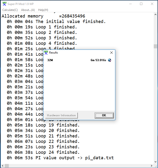
Super PI is a single threaded benchmark ideal for testing pure, single threaded x86 floating point performance and while most of the computing market has shifted towards multithreaded applications and more modern instruction sets, Super PI still remains quite indicative of CPU capability in specific applications such as computer gaming. The lesser the time is preferable.
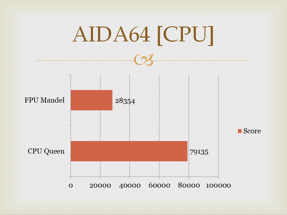
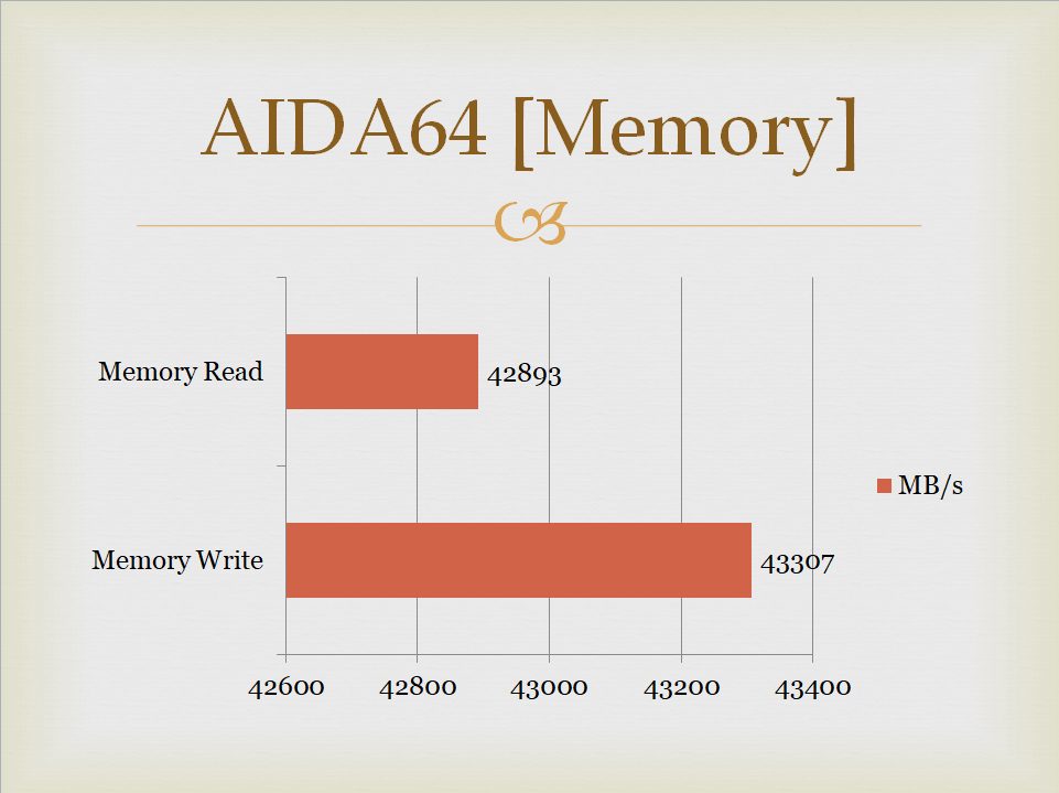
AIDA64 is another extensive application suite to measure the performance and testing the system’s stability. I used it to measure the CPU Queen, FPU Mandal and Memory bandwidth tests.
SiSandra is another comprehensive application suite to measure the performance of the various components of the PC and to check for any reported issues with them. It uses a graphical representation as well as the performance measure. I used it for CPU and Memory testing.
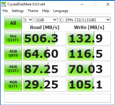
CrystalDiskMark is a popular tool to measure the sequential and Random Read and Write speeds of the storage drive(s).
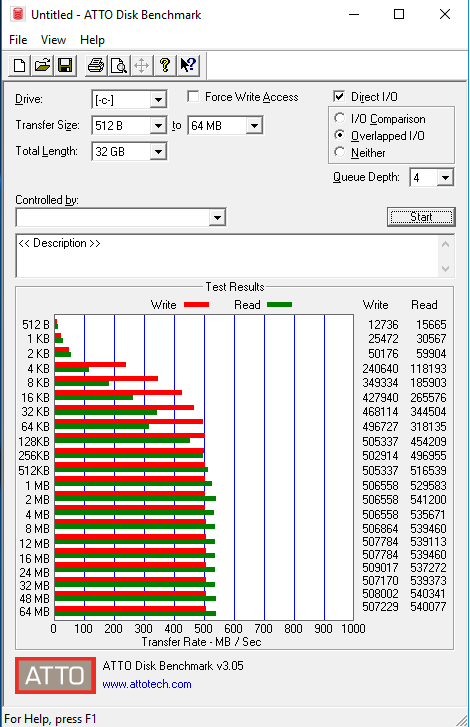
ATTO has created a widely-accepted Disk Benchmark freeware software to help measure storage system performance. As one of the top tools utilized in the industry, Disk Benchmark identifies performance in hard drives, solid state drives, RAID arrays as well as the host connection to attached storage.
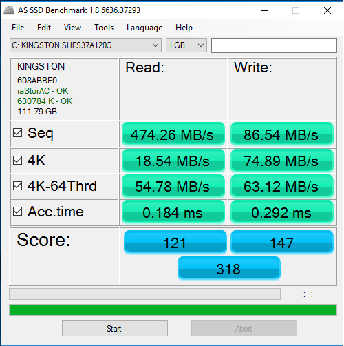
AS SSD software tests the sequential or random read/write performance of the storage drive(s) without using the cache. AS SSD Benchmark reads/writes a 1 GByte file as well as randomly chosen 4K blocks. Additionally, it performs the tests using 1 or 64 threads and it determines the SSD’s access time.
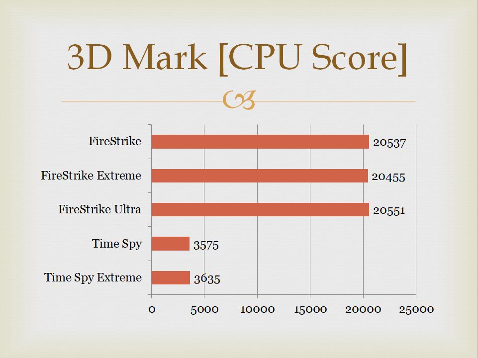
3DMark includes everything you need to benchmark your PC and mobile devices in one app. Whether you’re gaming on a smartphone, tablet, notebook, or a desktop gaming PC, 3DMark includes a benchmark designed specifically for your hardware. We are specifically showing the CPU score only in the graphs.
We have tested 4 games on the test build. All the games were tested with their highest graphics settings.

AiSuite
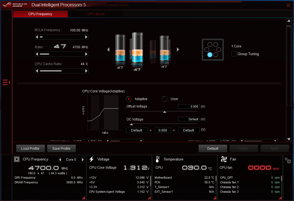
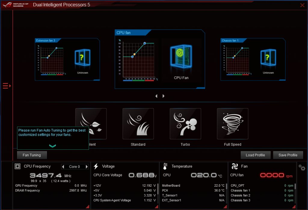
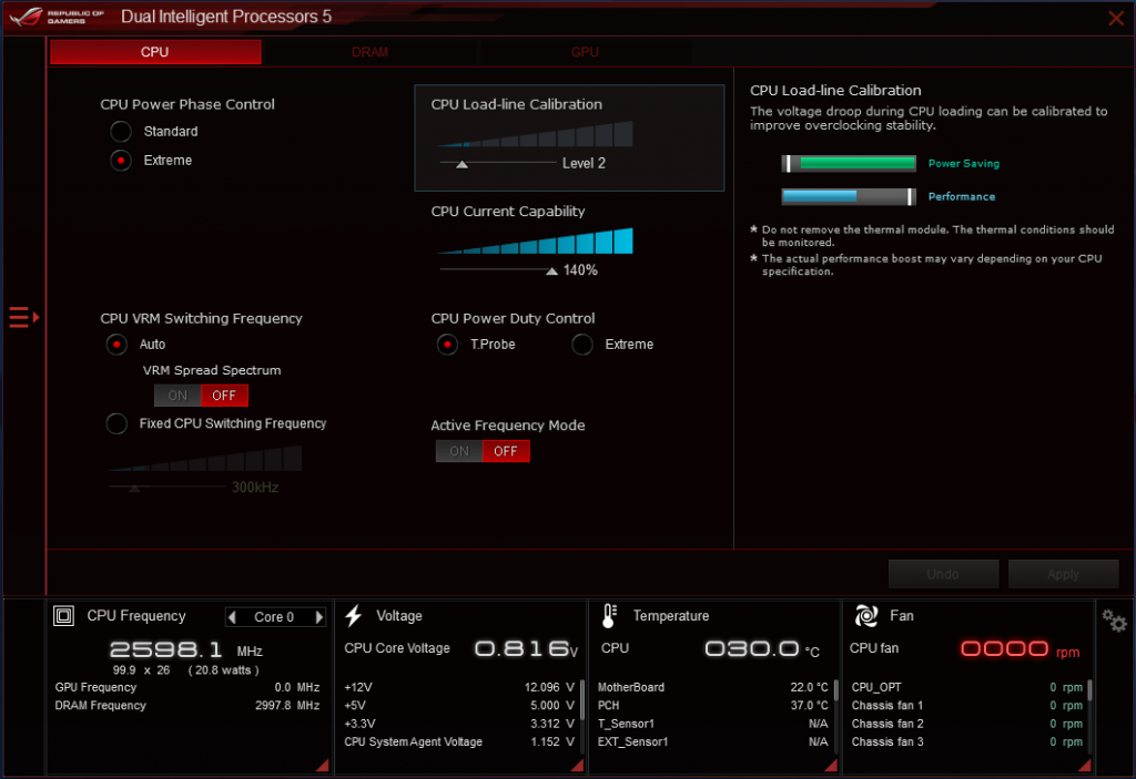
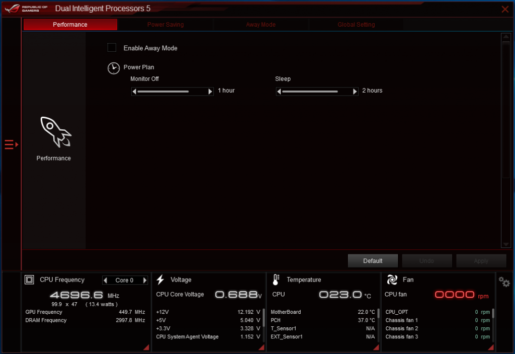
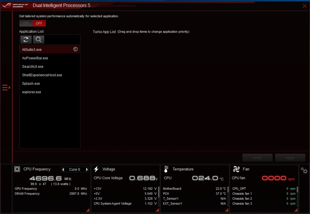
Asus has bundled many software in the provided CD disk. We’ll discuss AiSuite here as it is the main software when it comes to getting best of the best performance and fine tuning. The user can use this software to do literally anything ranging from overclocking to controlling fans to updating software and BIOS etc. The main interface has One Click Overclocking option on the top left side. Click it and 5-way digital optimization will start. There are three modes on its right side, namely: Performance, Power Saving and Away Mode. Away Mode is a more tightened version of the Power Saving mode. We’ve TPU, Fan Xpert and Digi VRM summaries on the main section. Turbo App status and EPU settings are on the right side of the main section. CPU Frequency, Voltages, Temperatures and Fan speeds are mentioned on the status bar located at the bottom of the interface. Clicking on the three bars and an arrow indicator on the left most side will open the menu list of the software. We’ve TPU, EPU, Digi+ VRM, Fan Xpert, PC Cleaner, EZ Update etc on the listing. Fan Xpert is a very handy tool and it can be used to configure each and every fan in the Chassis as per the user requirement. If you are not sure about the settings to be used then simply run the Fan Xpert Fan tuning wizard. The wizard will check the characteristics of each fan and set the profile accordingly. There are 4 pre-built profiles for the fans which are Silent, Standard, Turbo and Full speed. The graphical interface is available as well to set the fan curve. There are two modes, smart Mode with custom fan curve and RPM Fixed Mode which will set the one constant speed for the selected fan. TPU section provides comprehensive settings to overclock the CPU. We have the option of fine tuning single core or group of cores. Voltage can be set as Adaptive, offset or User where User means the manual Vcore. Digi+ VRM section contains settings like CPU Load Line Calibration, VRM Switching Frequency, CPU Power Phase control etc. Clicking on 5-Way Digital Optimization will start a tuning wizard that would overclock the CPU frequency with 100MHz at a time with stress test of 15 Seconds or user provided value on each iteration to determine the thermal characteristics and stability. The system will restart several times during the process. The process is fully automatic and user intervention is not needed. Each iteration shows the summary of the process in terms of Current-Voltage, Temperature and Power in addition to the Maximum values of each variable. Once the complete process is done, Summary will be produced. System Information shows the Motherboard, CPU and DRAM information. Turbo App boosts the performance of selected applications. PC Cleaner lets the user to get rid of junk files and to free the space taken by these files. EZ Update lets the user update the BIOS of the motherboard and other apps. USB BIOS Flashback lets the user to check and download the latest BIOS and copy it to the supported USB Flash drive which then can be used to update the BIOS by using the methods already described under BIOS section. File Transfer is another feature which is based on cloud computing. It lets the user transfer the files between supported mobile devices and the PC. I’ve used this utility to transfer files from and to my Android device to the PC. It needs an active WiFi connection to do that. Files can be shared using Could Go as well so as to make your files accessible from the cloud server.
Overclocking
We were not able to overclock this particular chip due to high thermals on the stock clocks. This chip with all cores on 4.7GHz was doing over 85°C under gaming and other loads. Hence, we did not attempt any overclocking on this chip. To put the matter into some perspective, this chip was being cooled by the Alphacool Eisbaer 360mm CPU cooler. This chip runs hot for it is like that and is a prime candidate for delidding which is not in the scope of this content.
[pros_cons id=”12″ asin=”B075RHWCC4″]Conclusion
Asus is not a un-known quantity in the market of PC Components and Peripherals and their ROG (Republic of Gamers) brand has earned them the respect and trust from the gamers and they have truly created a republic in which every Asus user is welcome though this Republic is for the Asus users only. ROG being their premium brand, Asus created Strix brand to target the middle market segment. Later on, they merged the Strix under the ROG branding giving the Strix users a sense of accomplishment for still being a part of the Republic. Asus ROG and ROG Strix line up of motherboards are feature rich with performance punch packed inside. Asus Strix Z370-E Gaming motherboard is the high end offering in the ROG Strix lineup. As is the case with the other models, this motherboard features the same intuitive UEFI BIOS with user friendly interface and easy to navigate through the menus. BIOS is also feature rich for novice and experienced users and has many functions like creating custom fan curve profile for each fan, taking picture of the BIOS screen and saving it to the USB Flash drive, Securely erasing the SSD, updating the BIOS from the Internet, GPU post to name a few. Of course it is needless to say that overclocking features are full of cream giving full control over every aspect of the motherboard and the CPU for the experienced user.
This motherboard has Intel LGA-1151 socket featuring the 14nm eight generation Coffee Lake CPUs from the Intel. Just a reminder that despite being a LGA-1151 socket, it does not support the KabyLake/SkyLake CPUs. Pins layout is same but their functions are different. This motherboard has 4 DIMM slots supporting only DDR4 DRAM modules with maximum of 64GB capacity and 4000MHz (OC) DRAM speed. This motherboard has total 7 PCIe Gen 3 slots with 4 of them being PCIe X1 rated, one is x16 rated which is electrically implemented and drawing PCIe lanes from the CPU. The other PCIe slot is X8 rated and the last one is PCIe X4 rated with PCIe lanes sharing with the Z370 chipset. In case of ywo way SLI or Cross Fire X the X16 slot will operate at X8 speed. In terms of storage, this motherboard has total of 6 SATA 6G ports from Intel Z370 chipset. It has two M.2 Sockets. One is located below the CPU Socket. It does not have heatsink cover and it is socket 3 with M key type 2242/2260/2280 storage devices using PCIe mode only. The other socket is located under the beautiful heatsink on the Z370 chip. It is socket 3 with M key type 2242/2260/2280 using SATA and PCIe X4 mode. Speaking of USB ports, we have 6 USB 3.0 ports coming from the Intel Z370 chipset and 6 USB 2.0 ports also coming from the Intel Z370 chipset. We also have a USB 3.1 Gen 2 port and two USB 3.1 Gen 1 ports coming from ASMedia controller. This board is Intel Optane Memory ready.
Speaking of the cooling solution, we have 4 4-pin PWM fan headers on this motherboard with a dedicated AIO_Pump header which is also 4-pin. In case you feel like short of fan headers there is also a 5-pin Fan Extension header on this motherboard. User can buy optional Fan Extension Hub accessory from Asus to be used with this motherboard. Upto 3 4-pin PWM fans and 2 thermal sensors can be connected on this hub. The hub draws power through SATA connector. Asus has implemented 4 thermal sensors on this motherboard and additionally there is T_Sensor connector to connect thermistor cable with it. This motherboard also has two 3D Mounts for 3D printed accessories. We have two AURA headers with +12V/G/R/B format and an addressable header with +5V/D//G format. There is a single lighting zone on this motherboard which is located on the rear I/O panel’s shroud. There are two aluminum made heatsink covers on the VRM and MOSFETs. It has TPM connector, Serial Com connector and front panel audio connector as well. There is no Q-Debug LED on this motherboard. There are 4 LEDs on the right side of the PCB with each LED corresponding to Boot, VGA, DRAM, and CPU. In case of any issue, the corresponding LED remains lit. Alternatively, user can connect a speaker on the system panel connector and trouble shoots the issues using the beep codes which is old school method these days. It features Intel 1219V Gb LAN using LANGuard and GameFirst IV. It features SupremeFX S1220 Codec using ES9023P High Definition DAC with 120dB SNR stereo playback and 113dB SNR recording input. Sonic Studio III and Sonic Radar III are bundled software to augment the hardware functionality. We have 10 power phases on this motherboard with adequate controller to regulate various aspects of the power delivery and regulation. This motherboard has 2×2 WiFi module with stylish designed antenna in Asus branding. This WiFi implementation is supporting a/b/g/n/ac and supports dual band frequency 2.4/5GHz with MU-MIMO. The motherboard carries limited 3 years warranty.
Our experience with the motherboard has been smooth and flawless. First boot was a success. The BIOS has no glitch. BIOS has a user friendly interface and the Asus users would not find anything different in the layout making the life easier for the user. Bundle software are handy and offers lot of functionality based on the respective hardware components.
Asus ROG Strix Z370-E Gaming motherboard is the high end motherboard in the ROG Strix line up. Don’t confuse it with ROG only motherboards. This motherboard is features rich and has adequate power delivery circuitry to drive your daily needs. This is further augmented by the on-board LED zone and two AURA sync headers as well as an addressable RGB header. This motherboard comes recommended by us.
Asus ROG Strix Z370-E Gaming X Motherboard Review
Design - 9
Features - 9
Performance - 9
Value - 8.5
Quality - 9
8.9
Thanks! Do share your feedback with us. ⚡
How can we make this post better? Your help would be appreciated. ✍